|
CARTER CARBURETOR CORPORATION, ST. LOUIS, MO., U. S. A. Page
3
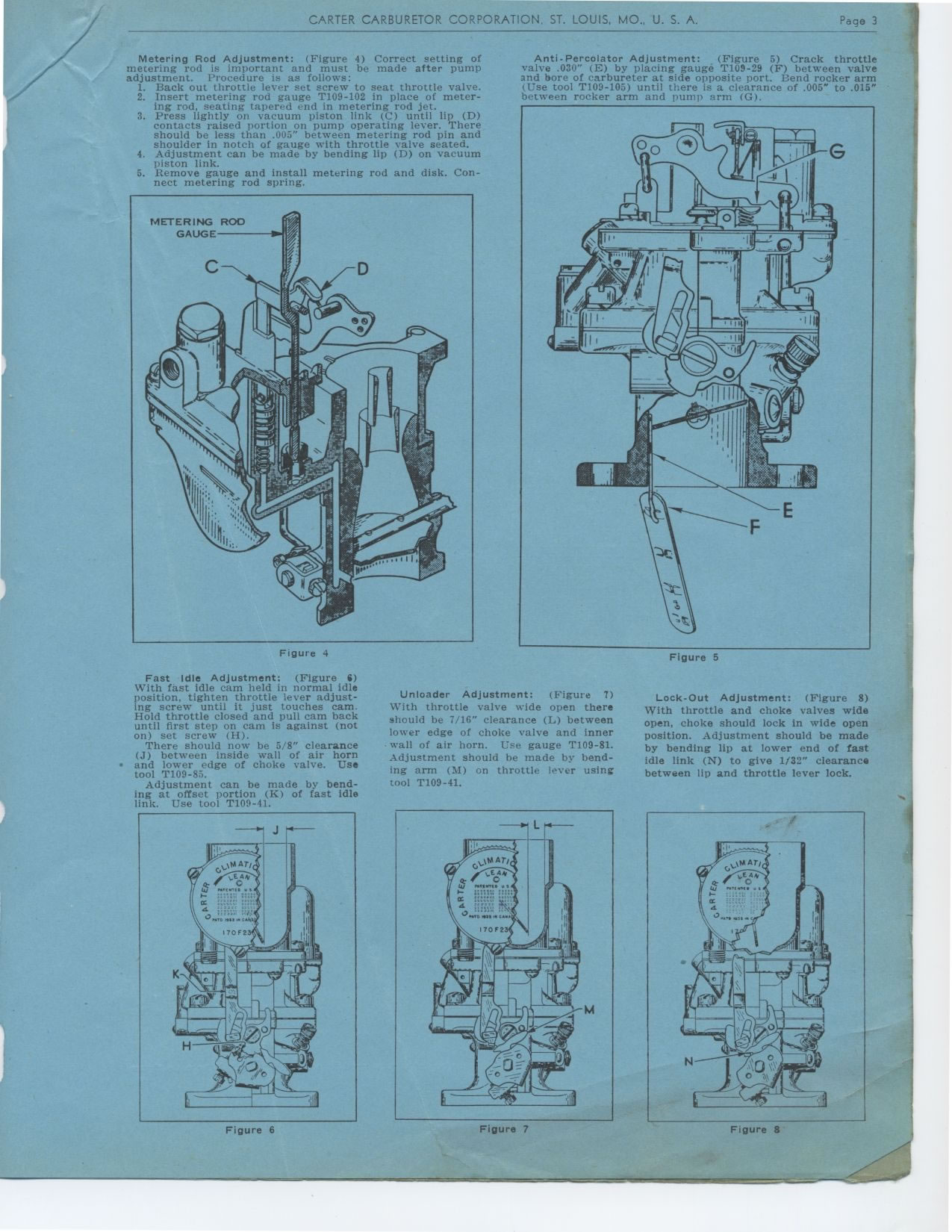
Metering Rod Adjustment: (Figure 4) Correct setting of metering rod is important
and must be made after pump adjustment. Procedure is as follows:
1. Back out throttle lever set screw to seat throttle valve.
2. Insert metering rod gauge T109-102 in place of metering rod, seating tapered
end in metering rod jet.
3. Press lightly on vacuum piston link (C) until lip (D) contacts raised
portion on pump operating lever. There should be less than .005" between
metering rod pin and shoulder in notch of gauge with throttle valve seated.
4. Adjustment can be made by bending lip (D) on vacuum piston link.
5. Remove gauge and install metering rod and disk. Connect metering rod spring.
Figure 4
Anti-Percolator Adjustment: (Figure 5) Crack throttle valve .030" (E)
by placing gauge T109-29 (F) between valve and bore of carbureter at side
opposite port. Bend rocker arm Use tool T109-105) until there is a clearance
of .005" to .015" between rocker arm and pump arm (G).
Figure 5
Fast Idle Adjustment: (Figure 6) With fast idle cam held in normal idle position,
tighten throttle lever adjusting screw until it just touches cam. Hold throttle
closed and pull cam back until first step on cam is against (not on) set
screw (H).
There should now be 5/8" clearance (J) between inside wall of air horn
• and lower edge of choke valve. Use tool T109-85.
Adjustment can be made by bending at offset portion (K) of fast idle link.
Use tool T109-41.
Unloader Adjustment: (Figure 7) With throttle valve wide open there should
be 7/16" clearance (L) between lower edge of choke valve and inner wall
of air horn. Use gauge T109-81. Adjustment should be made by bending arm
(H) on throttle lever using tool T109-41.
Lock-Out Adjustment: (Figure 8) With throttle and choke valves wide open,
choke should lock in wide open position. Adjustment should be made by bending
lip at lower end of fast idle link (N) to give 1/32" clearance between
lip and throttle lever lock.
Figure 6
Figure 7
Figure 8
|