|
CARTER CARBURETOR CORPORATION, ST. LOUIS, MO., U. S. A.
Form 6406D—Canadian
HUDSON 4545
December, 1939
Reprinted February, 1946
tAR AND MOTOR NUMBERS
1940—40101 and Higher
1941—10101 and Higher
1942—20101 and Higher
HUDSON
40 SIX 1940
10 SIX 1941
20 SIX 1942
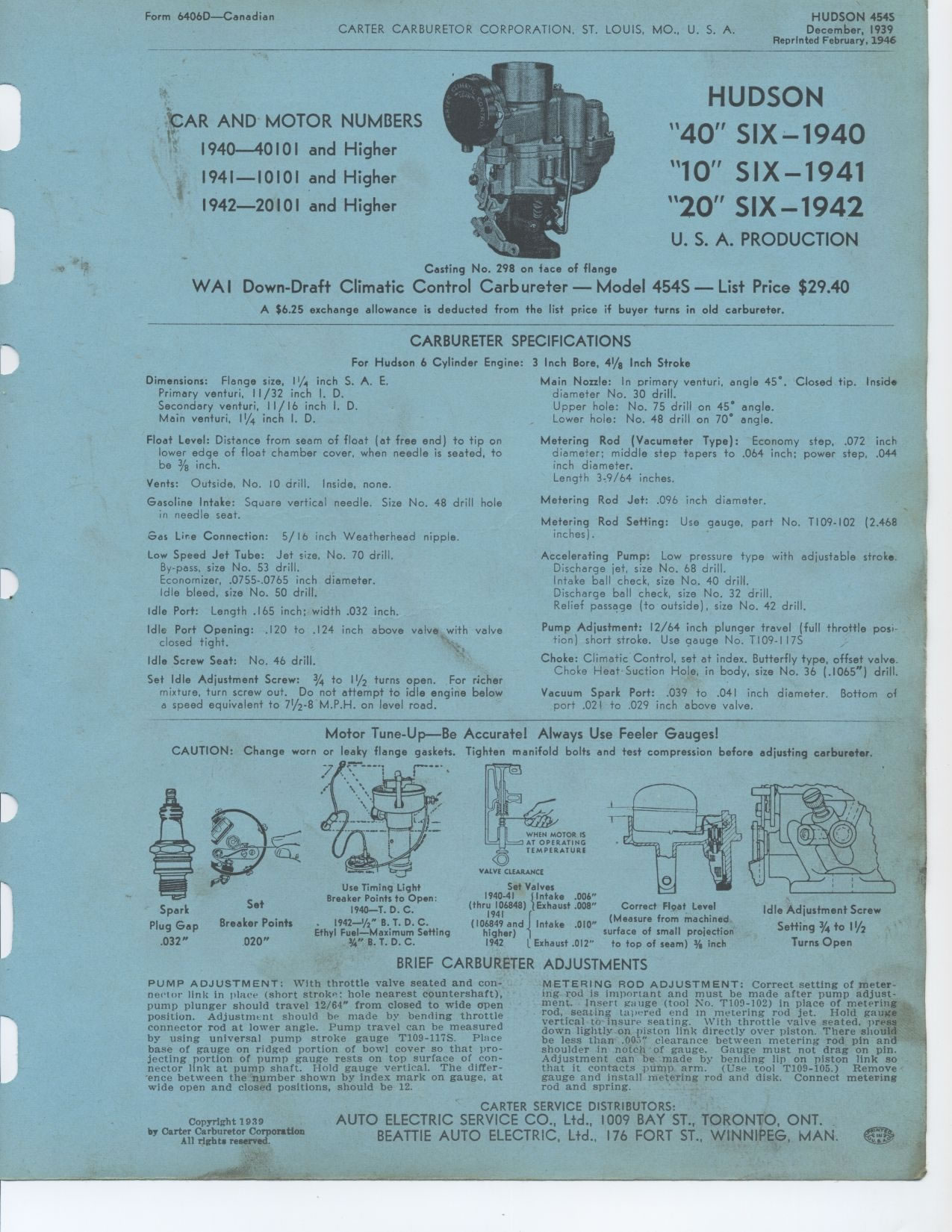
Casting No. 298 on face of flange
WA 1 Down-Draft Climatic Control Carbureter — Model 454S — List
Price $29.40
A $6.25 exchange allowance is deducted from the list price if buyer
turns in old carbureter.
U. S. A. PRODUCTION
CARBURETER SPECIFICATIONS
For Hudson 6 Cylinder Engine: 3 Inch Bore, 41/8 Inch Stroke
Dimensions: Flange size, 1¼ inch S. A. E. Primary venturi, 1
1 /32 inch I. D.
Secondary venturi, 11/16 inch I. D. Main venturi, 11/4 inch I. D.
Float Level: Distance from seam of float (at free end) to tip on lower
edge of float chamber cover, when needle is seated, to be 3/8 inch.
Vents: Outside, No. 10 drill. Inside, none.
Gasoline Intake: Square vertical needle. Size No. 48 drill hole in
needle seat.
Gas Lire Connection: 5/ 16 inch Weatherhead nipple.
Low Speed Jet Tube: Jet size, No. 70 drill. By-pass, size No. 53 drill.
Economizer, .0755-.0765 inch diameter. Idle bleed, size No. 50 drill.
Idle Port: Length .165 inch; width .032 inch.
Idle Port Opening: .120 to .124 inch above valve closed tight.
Idle Screw Seat: No. 46 drill.
Set Idle Adjustment Screw: 3/4 to 11/2 turns open. For richer mixture,
turn screw out. Do not attempt to idle engine below a speed equivalent
to 71/2-8 M.P.H. on level road.
Main Nozzle: In primary venturi, angle 45°. Closed tip. Inside
diameter No. 30 drill.
Upper hole: No. 75 drill on 45° angle.
Lower hole: No. 48 drill on 70° angle.
Metering Rod (Vacumeter Type): Economy step, .072 inch diameter; middle
step tapers to .064 inch; power step, .044 inch diameter.
Length 3-9/64 inches.
Metering Rod Jet: .096 inch diameter.
Metering Rod Setting: Use gauge, part No. T109-102 (2.468 inches).
Accelerating Pump: Low pressure type with adjustable stroke. Discharge
jet, size No. 68 drill.
Intake ball check, size No. 40 drill.
Discharge ball check, size No. 32 drill.
Relief passage (to outside), size No. 42 drill.
Pump Adjustment: 12/64 inch plunger travel (full throttle position)
short stroke. Use gauge No. T109-I 17S
Choke: Climatic Control, set at index. Butterfly type, offset valve.
Choke Heat Suction Hole, in body, size No. 36 (.1065") drill.
Vacuum Spark Port: .039 to .041 inch diameter. Bottom of port .021
to .029 inch above valve.
with valve
Motor Tune-Up—Be Accurate! Always Use Feeler Gauges!
CAUTION: Change worn or leaky flange gaskets. Tighten manifold bolts
and test compression before adjusting carbureter.
BRIEF CARBURETER ADJUSTMENTS
VALVE CLEARANCE
Set Valves
1940-41 (Intake .006" (thru 106848) (Exhaust .008" 1941
(106849 and Intake .010" higher)
1942 L Exhaust .012"
Correct Float Level (Measure from machined surface of small projection
to top of seam) 3/6 inch
Idle Adjustment Screw
Setting 3/4 to I I/2
Turns Open
Spark Set
Plug Gap Breaker Points
.032" 020"
•
ILO'
Use Timing Light
Breaker Points to Open:
1940-T. D. C.
1942—1/2" B. T. D. C.
Ethyl Fuel—Maximum Setting
3A"B.T.D.C.
PUMP ADJUSTMENT: With throttle valve seated and connector link in place (short
stroke: hole nearest countershaft), pump plunger should travel 12/64" from
closed to wide open position. Adjustment should be made by bending
throttle connector rod at lower angle. Pump travel can be measured
by using universal pump stroke gauge T109-117S. Place base of gauge
on ridged portion of bowl cover so that projecting portion of pump
gauge rests on top surface of connector link at pump shaft. Hold
gauge vertical. The difference between the number shown by index
mark on gauge, at wide open and closed positions, should be 12.
METERING ROD ADJUSTMENT: Correct setting of metering rod is important
and must be made after pump adjustment. Insert gauge (tool No. T109-102)
in place of metering rod, seating tapered end m metering rod jet. Hold
gauge vertical to insure seating. With throttle valve seated, press
down lightly on piston link directly over piston. There should be less
than .00 clearance between metering rod pin and shoulder in notch of
gauge. Gauge must not drag on pin. Adjustment can be made by bending
lip on piston link so that it contacts pump arm. (Use tool T109-105.)
Remove gauge and install metering rod and disk. Connect metering rod
and spring.
Copyright 1939
|