|
ANTI-PERCOLATOR ADJUSTMENT: Crack throttle valve .030" by
placing gauge T10'l-29 between valve and bore of carbureter (side opposite
port). Bend rocker arm (use tool T109-105) until there is a clearance of
.005" to .015" between rocker arm and pump arm.
FAST IDLE ADJUSTMENT: With fast Idle cam held in normal Idle position, tighten
throttle lever adjusting screw until It just seats against cam. Hold throttle
lever closed and pull cam back until first (or lower) step on cam is against
(not on) set screw.
There should now be %" clearance between inside wall of air horn and
lower edge of choke valve. (Use tool T109-85.) Adjustment can be made by
bending at offset portion of fast idle link. (Use tool TI09-4I.)
UNLOADER ADJUSTMENT. With throttle valve wide open there should be 7/16" clearance
between lower edge of choke valve and inner wall of air horn. (Use tool T109-81.)
Adjustment should be made by bending cam on throttle lever.
(Use tool T109-41.)
LOCK-OUT ADJUSTMENT: With throttle and choke valves wide open, choke should
lock in wide open position. Adjustment should be made by bending lip at lower
end of fast idle link to give 1/32" clearance between lip and throttle
lever lock, with throttle and choke valves held wide open. (Use tool T109-105.)
TRIP LEVER ADJUSTMENT: After making all choke linkage adjustments, hold choke
valve tightly closed with pin on fast idle cam resting at bottom of slot
in fast idle link. Adjust stop for trip lever to give .010" clearance
between fast idle cam and trip lever lip. (See cut.)
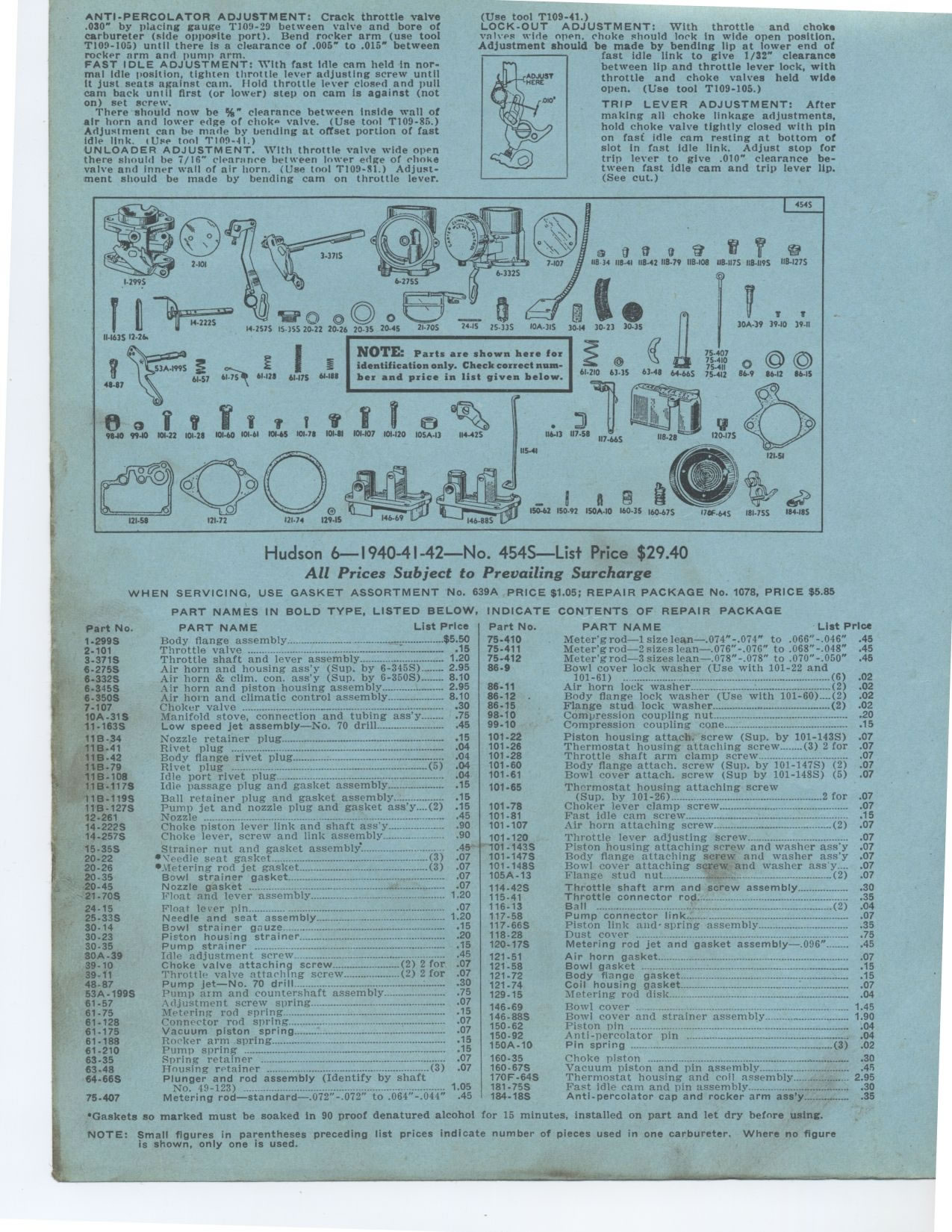
NOTE: Parts are shown here for identification only. Check correct number
and price in list given below.
Hudson 6 1940 1941 1942 No. 454S
—List Price $29.40
All Prices Subject to Prevailing Surcharge
WHEN SERVICING, USE GASKET ASSORTMENT No. 639A PRICE $1.05; REPAIR PACKAGE
No. 1078, PRICE $5.85
PART NAMES IN BOLD TYPE, LISTED BELOW, PART NAME List Price
Body flange assembly .. °° - -------------c •---°----$5.50
Throttle valve -------° 15
Throttle shaft and lever assembly 1.20
Air horn and housing ass'y (Sup. by 6-345S) 2.95
Air horn & clim. con. ass'y (Sup. by 6-350S) 8.10
Air horn and piston housing assembly 2.95
Air horn and climatic control assembly 8.10
Choker valve ------ ----- .... ...° -30
Manifold stove, connection and tubing ass'y 75
Low speed jet assembly—No. 70 drill 45
11B-34 Nozzle retainer plug 15
11B-41 Rivet plug 04
11B-42 Body flange rivet plug : 04
11B-79 Rivet plug (5) .04
11B-108 Idle port rivet plug ..............................................
.04
11B-1175 Idle passage plug and gasket assembly 15
11B-119S Ball retainer plug and gasket assembly ..: 15
11B-127S Pump jet and nozzle plug and gasket ass'y....(2) 15
12-261 Nozzle ----- ........-_._...---.-. .....---° ...... .45
14-222S Choke piston lever link and shaft ass'y 90
14-257S Choke lever, screw and link assembly 90
15.35S Strainer nut and gasket assembly 45
20-22 •\eedie seat gasket (3) 07
20-26 *Metering rod jet gasket (3) 07
20.35 Bowl strainer gasket 07
20-45 Nozzle gasket ------------ -°--- 07
21-70S Float and lever assembly 1,20
24.15 Float lever pin ,07
25-33S Needle and seat assembly 1 20
30.14 Bowl strainer gauze 15
30-23 Piston housing strainer 20
30-35 Pump strainer --------- 15
30A-39 Idle adjustment screw 45
39-10 Choke valve attaching screw (2) 2 for 07
39.11 Throttle valve attaching screw (2) 2 for 07
48-87 Pump jet—No. 70 drill 30
53A-199S Pump arm and countershaft assembly 75
61.57 Adjustment screw spring 07
61-75 Metering rod spring --°° 15
61-128 Connector rod spring 07
61-175 Vacuum piston spring 07
61-188 Rocker arm spring 15
61.210 Pump spring °° ------ -°--- ° ........ .15
63.35 Spring retainer ------ 07
63.48 Housing retainer .(3) .07
64-66S Plunger and rod assembly (Identify by shaft
No. 49-123) _- 1.05
75-407 Metering rod—standard—.072"-.072" to .064"-.044" .45
'Gaskets so marked must be soaked in 90 proof denatured alcohol for 15 minutes,
installed on part and let dry before using.
NOTE: Small figures in parentheses preceding list prices indicate number
of pieces used in one carbureter. Where no figure is shown, only one is used.
INDICATE CONTENTS OF REPAIR PACKAGE
Part No. 1-299S 2-101 3.3715 6-275S 6.332S 6-345S 6-350S 7-107 10A-31S 11.163S
Part No. 75.410 75.411 75-412 86-9
86.11 86-12 . 86-15 98-10 99-10
101-22 101.26 101-28 101.60 101-61 101-65
101-78 101.81 101.107
101-120 101 .143S 101-147S 101.148S 105A-13
114.42S 115-41 116-13 117.58 117.66S 118.28 120-175
121-51 121.58 121.72 121-74 129-15
146.69 146-88S 150.62 150.92 150A-10
160-35 160.67S 170E-64S 181.755 184-18S
PART NAME List Price Meter'g rod—1 size lean—.074"-.074" to
.066"-.046" .45 Meter'g rod—2 sizes Lean—.076"-.076" to
.068"-.048" .45 Meter'g rod-3 sizes lean—.0 78"-.078" to
.070"-.050" .45 Bowl cover lock washer (Use with 101-22 and
101-61) --- ......................................(6) .02
Air horn lock washer (2) .02
Body flange lock washer (Use with 101-60) (2) .02
Flange stud lock washer (2) .02
Compression coupling nut 20
Compression coupling cone 15
Piston housing attach. screw (Sup. by 101-1435) 07
Thermostat housing attaching screw (3) 2 for 07
Throttle shaft arm clamp screw 07
Body flange attach. screw (Sup. by 101-1475) (2) 07
Bowl cover attach. screw (Sup by 101-148S) (5) 07
Thermostat housing attaching screw
(Sup. by 101-26) 2 for 07
Choker lever clamp screw 07
Fast idle cam screw 15
Air horn attaching screw (2) 07
Throttle lever adjusting screw 07
Piston housing attaching screw and washer ass'y 07
Body flange attaching screw and washer ass'y 07
Bowl cover attaching screw and washer assy.... .07
Flange stud nut (2) 07
Throttle shaft arm and screw assembly 30
Throttle connector rod 35
Ball .--- ----------------- _.. .(2) 04
Pump connector link 07
Piston link and- spring assembly 35
Dust cover ,75
Metering rod jet and gasket assembly—.096" 45
Air horn gasket 07
Bowl gasket : ----------- 15
Body flange gasket 15
Coil housing gasket 07
Metering rod disk 04
Bowl cover 1.45
Bowl cover and strainer assembly 1.90
Piston pin 04
Anti-percolator pin 04
Pin spring °° ----°---°--- (3) 02
Choke piston ` 30
Vacuum piston and pin assembly 45
Thermostat housing and coil assembly 2.95
Fast idle cam and pin assembly 30
Anti-percolator cap and rocker arm ass'y 35
|