|
CARTER CARBURETOR CORPORATION, ST. LOUIS, MO., U. S. A.
Form 64538-Canadian
HUDSON, 1937 1940
July, 1940
Reprinted May, 1946
Year and Carbu- Casting Price Ex-
Model refer No. Starting Motor No. Number List change
1937-6 CyI. 344S-377S 90000 and higher 148 Sup. by 461 S
1937-8 Cyl. 344S-377S 18000 and higher 148 Sup. by 46I S
1938-6 CyI. 402S 98000 and higher* 148 XSup. by 46I S
1938-8 Cyl. 402S 35000 and higher* 148 XSup. by 46I S
1939-6 Cyl. 402S 93101 and higher 148 XSup. by 46I S
1939-8 Cyl. 402S 95101 and higher 148 XSup. by 46I S
1939-"93" 6 430S 938310 and higher 199 XSup. by 461 S
1939-"95" 8 430S 958632 and higher 199 XSup. by 46I S
1939-"97" 8 430S 978763 and higher 199 XSup. by 46I S
1940-"41" 6 430SV 41 101 and higher 199 XSup. by 4615
1940-"43" 6 430SV 43101 and higher 199 XSup. by 461S
1940-8 Cyl. t455S 31 16 and higher 279 38.20 7.50
1940-6 Cyl. -}461 S 44101 and higher 286 38.20 7.50
1940-6 Cyl. t461 S 47101 and higher 286 38.20 7.50
*After 6 cylinder Car No. 94371, or 8 cylinder Car Not. 98227, 99227, 101227,
Motor Nos. same as Car Nos.
t A few early 1941 Hudson cars were equipped with these carbureters.
XWhen replacing 402S, 430S and 430SV with 4615, use I I B-33 plug in vacuum
spark port.
MOTOR TUNE-UP - BE ACCURATE! ALWAYS USE FEELER GAUGES!
CAUTION: Change worn or leaky flange gaskets. Tighten ma nifold bolts
and test compression before adjusting carbureter.
YEAR
SET VALVES FLOAT LEVEL
(Remove
Cork Gasket)
BREAKER IGNITION TIMING
POINTS Breaker Points
to Open
SPARK
PLUG
GAP
IDLE SCREW
SETTING
(Turns Open)
Intake Exhaust
937-6 CyI. .025" .020" Top Dead Center .006" .008" 15/64" %4
to 3/4
937-8 CyI... .025" .017" Top Dead Center .006" .008" 15/64" %4
to 3/4
1938-6 Cyl. . .032" .020" Top Dead Center .006" .008" 15/64" %4
to /4
1938-8 CyI.. .032" .017" Top Dead Center 006" .008" 15/64" V4
to 3/4
1939-6 Cyl... .032" .020" Top Dead Center . )06" .008" 3/32" %4
to 1
939-8 Cyl.... .032" .017" Top Dead Center .006" .008" 3/32" to
1940-6 Cyl.__. .032" .020" Top Dead Center .006" .008" 3/32" I/4
to I %4
1940-8 Cyl.... .032" .017" Top Dead Canter .006" .008" 3/32" 1/2
to 1I/2
WDO DUAL CARBURETER INDEX AND PRICE LIST
HUDSON
SIXES & EIGHTS
1937-40
(EARLY 1941)
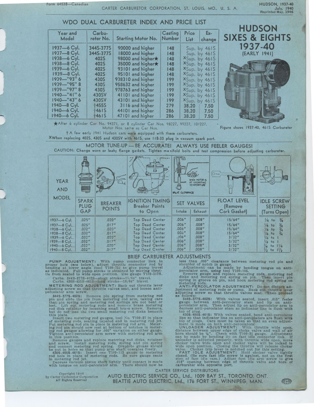
Figure shows 1937-40, 4615 Carburetor
BRIEF CARBURETER
PUMP ADJUSTMENT: With pump connector link in proper hole (see below),
adjust throttle connector rod by bending at lower angle (tool T109-75)
to give pump travel as indicated. Full pump stroke is obtained by moving
throttle from seated to wide open position. Use gauge T109-117S.
Carbs. 344S-377S-402S-short stroke-15/64" travel.
Curbs. 430S-4555-4615-long stroke-18/64" travel.
METERING ROD ADJUSTMENT: Back out throttle lever adjusting screw so that
throttle valves seat, and loosen anti-percolator arm screw.
344S-377S-4025: Remove pin spring from metering rod pin and slide the
pin from metering rod arm, taking care that pin spring and metering rod
springs are not bent or lost. Lift out metering rods and remove brass
metering rod disk retainer by loosening small brass screw. Remove, but
do not lose the two small metering rod disks beneath this plate.
Insert two metering rod gauges, tool No. T109-27 in place of metering
rods, seating tapered end in metering rod jet. Put metering rod pin in
place in metering rod arm. Metering rod pin should now rest at bottom
of notches in metering rod gauges allowing for .005" variation on either gauge. Tighten anti-percolator arm
screw with metering rod arm in this position.
Remove gauges and replace metering rod disks, retainer and screw. Install
metering rods, spring and pin spring and connect metering rod spring.
Graphite grease should be put in holes so that pump arm shaft operates
freely.
430S-455S-461S: Insert one T109-113 gauge in metering rod hole in place
of metering rods. Be sure gauge seats in metering rod jet.
Depress vacuum piston shaft lightly until contact is made with tongue
on anti-percolator arm. There should now be
ADJUSTMENTS
less than .005" clearance between metering rod pin and shoulder of notch
in gauge.
Adjustment can be made by bending tongue on anti-percolator arm, using
tool T109-105.
Remove gauge and replace metering rods, metering rod disks and metering
rod spring on pin. Then insert pin spring in groove on pin, and hook
metering rod spring on metering rods.
ANTI-PERCOLATOR ADJUSTMENT: Do not disturb adjustment of metering rods
or pump. Back out throttle lever adjusting screw so that throttle valves
seat. Then proceed as follows:
344S-377S-402S: With valves seated, insert .015" feeler gauge between anti-percolator
stem and lip on anti-percolator arm. Then adjust lip on anti-percolator arm to
depress anti-percolator stem so indicator line is flush with top of plug.
430S-455S-461S: With valves seated, bend anti-percolator lips so that
indicator line on anti-percolators are flush with top of plugs. Care
must be taken so that an even adjustment is made on both anti-percolators:
UNLOADER ADJUSTMENT: With throttle wide open, distance between upper
edge of choke valve and wall of air horn should be 1/4". Check with T109-31 gauge.
Adjustment can be made by bending lip on fast idle connector link. If unloader
is adjusted properly, with throttle wide open, move choker valve wide open and
choker valve will be locked in wide open position. Closing the throttle will
release choker valve. Choker trip lever is notched out for this setting.
FAST IDLE ADJUSTMENT: Hold choker valve tightly closed. (Be sure fast
idle screw is against, not on the first step of fast idle cam.) Adjust
fast idle arm screw to give .018" opening between edge of throttle valve and bore of carburetor
side opposite port.
Copyright 1940
|