|
Form 6281 B— Canadian
CARTER CARBURETOR CORPORATION, ST. LOUIS, MO., U. S. A.
MACK 380S
August, 1937
Reprinted March, 1945
CAR SERIAL NUMBERS 6EJ I SDH —I 00I and higher 6EJ I S —I 001
and higher 6EJ I SD —I 001 and higher
MOTOR SERIAL NUMBERS
EJ — 101 and higher
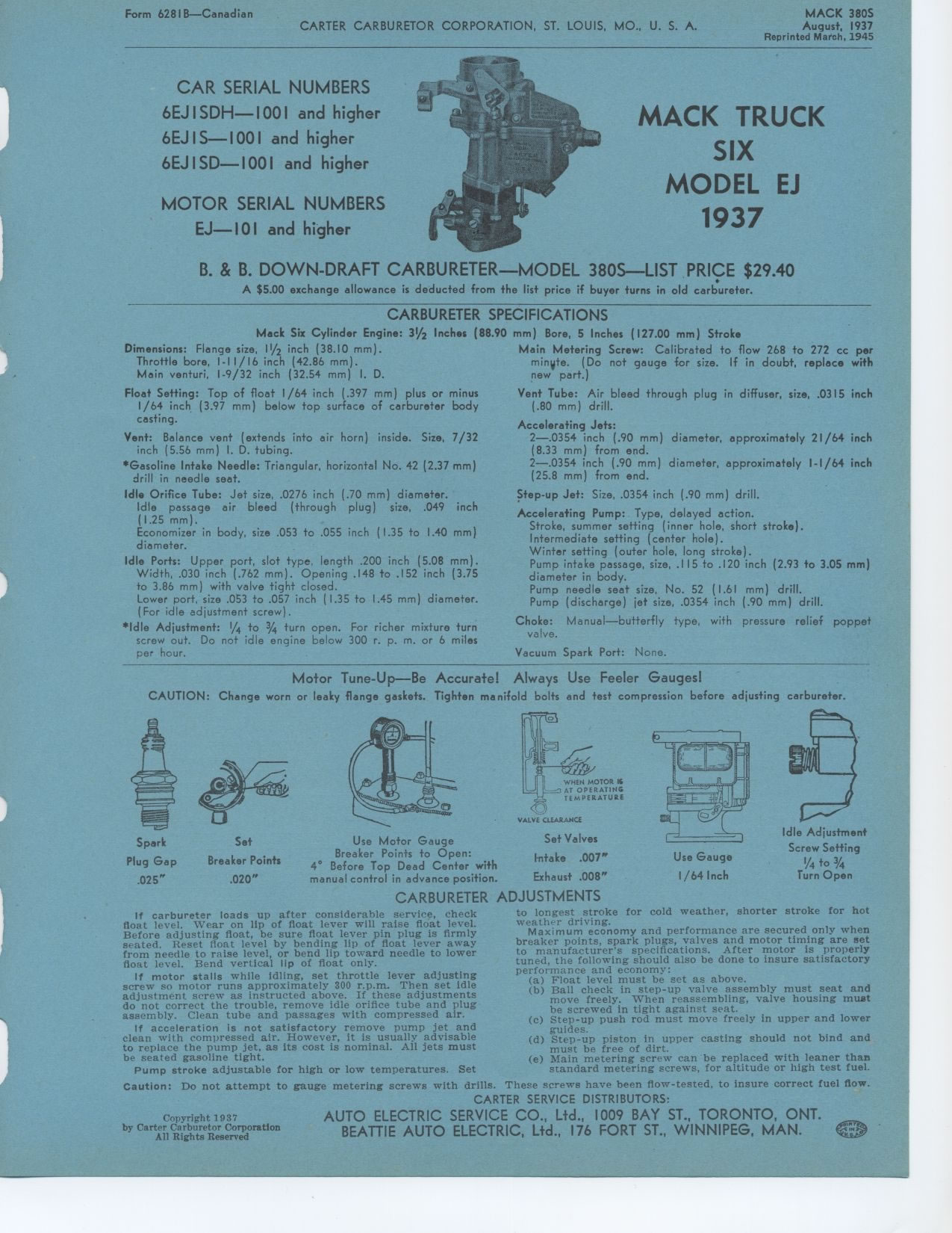
B. & B. DOWN-DRAFT CARBURETER — MODEL 380S —LIST PRICE $29.40
A $5.00 exchange allowance is deducted from the list price if buyer turns
in old carbureter.
CARBURETER SPECIFICATIONS
Mack Six Cylinder Engine: 31/2 Inches (88.90 mm) Bore, 5 Inches (127.00 mm)
Stroke
MACK TRUCK
SIX
MODEL EJ
1937
Dimensions: Flange size, 11/2 inch (38.10 mm). Throttle bore, 1-11/16 inch
(42.86 mm). Main venturi, 1-9/32 inch (32.54 mm) I. D.
Float Setting: Top of float 1/64 inch (.397 mm) plus or minus 1/64 inch (3.97
mm) below top surface of carbureter body casting.
Vent: Balance vent (extends into air horn) inside. Size, 7/32 inch (5.56
mm) I. D. tubing.
*Gasoline Intake Needle: Triangular, horizontal No. 42 (2.37 mm) drill in
needle seat.
Idle Orifice Tube: Jet size, .0276 inch (.70 mm) diameter.
Idle passage air bleed (through plug) size, .049 inch (1.25 mm).
Economizer in body, size .053 to .055 inch (1.35 to 1.40 mm) diameter.
Idle Ports: Upper port, slot type, length .200 inch (5.08 mm). Width, .030
inch (.762 mm). Opening .148 to .152 inch (3.75 to 3.86 mm) with valve tight
closed.
Lower port, size .053 to .057 inch (1.35 to 1.45 mm) diameter. (For idle
adjustment screw).
*Idle Adjustment: 1/4 to 3/4 turn open. For richer mixture turn screw out.
Do not idle engine below 300 r. p. m. or 6 miles per hour.
Main Metering Screw: Calibrated to flow 268 to 272 cc per minWte. (Do not
gauge for size. If in doubt, replace with new part.)
Vent Tube: Air bleed through plug in diffuser, size, .0315 inch (.80 mm)
drill.
Accelerating Jets:
2—.0354 inch (.90 mm) diameter, approximately 21/64 inch (8.33 mm)
from end.
2—.0354 inch (.90 mm) diameter, approximately 1-I/64 inch (25.8 mm)
from end.
Step-up Jet: Size, .0354 inch (.90 mm) drill.
Accelerating Pump: Type, delayed action.
Stroke, summer setting (inner hole, short stroke). Intermediate setting (center
hole). Winter setting (outer hole, long stroke).
Pump intake passage, size, .115 to .120 inch (2.93 to 3.05 mm) diameter in
body.
Pump needle seat size, No. 52 (1.61 mm) drill. Pump (discharge) jet size,
.0354 inch (.90 mm) drill.
Choke: Manual — butterfly type, with pressure relief poppet valve.
Vacuum Spark Port: None.
Motor Tune - Up— Be Accurate! Always Use Feeler Gauges!
CAUTION: Change worn or leaky flange gaskets. Tighten manifold bolts and
test compression before adjusting carbureter.
Use Gauge 1/64 Inch
Spark Set
Plug Gap Breaker Points
.025" .020"
Use Motor Gauge
Breaker Points to Open:
4° Before Top Dead Center with
manual control in advance position.
WHEN MOTOR K
AT OPERATING
TEMPERATURE
VALVE CLEARANCE
Set Valves Intake .007" Exhaust .008"
Idle Adjustment
Screw Setting
1/4 to 3/4
Turn Open
CARBURETER ADJUSTMENTS
If carbureter loads up after considerable service, check float level. Wear
on lip of float lever will raise float level. Before adjusting float, be
sure float lever pin plug is firmly seated. Reset float level by bending
lip of float lever away from needle to raise level, or bend lip toward needle
to lower float level. Bend vertical lip of float only.
If motor stalls while idling, set throttle lever adjusting screw so motor
runs approximately 300 r.p.m. Then set idle adjustment screw as instructed
above. If these adjustments do not correct the trouble, remove idle orifice
tube and plug assembly. Clean tube and passages with compressed air.
If acceleration is not satisfactory remove pump jet and clean with compressed
air. However, it is usually advisable to replace the pump jet, as its cost
is nominal. All jets must be seated gasoline tight.
Pump stroke adjustable for high or low temperatures. Set
to longest stroke for cold weather, shorter stroke for hot weather driving.
Maximum economy and performance are secured only when breaker points, spark
plugs, valves and motor timing are set to manufacturer's specifications.
After motor is properly tuned, the following should also be done to insure
satisfactory performance and economy:
(a) Float level must be set as above.
(b) Ball check in step-up valve assembly must seat and move freely. When
reassembling, valve housing must be screwed in tight against seat.
(c) Step-up push rod must move freely in upper and lower guides.
(d) Step-up piston in upper casting should not bind and must be free of dirt.
(e) Main metering screw can be replaced with leaner than standard metering
screws, for altitude or high test fuel.
Copyright 1937
by Carter Carburetor Corporation
All Rights Reserved
Caution: Do not attempt to gauge metering screws with drills. These screws
have been flow-tested, to insure correct fuel flow. CARTER SERVICE DISTRIBUTORS:
|