|

metering Hod Adjustment: Correct setting of metering roo. is
important and must be made after pump adjustment. Insert gauge (tool No.
T109-102) in place of metering rod, seating tapered end in metering rod jet.
Hold gauge vertical to insure seating. With throttle valve seated there should
be less than .005" clearance between pin in pump arm and shoulder of
notch in gauge. Gauge should not drag on pin. Adjustment should he made by
bending metering rod pin portion of pump arm up or down.
Remove gauge, and install metering rod and disk. Connect metering rod spring.
Anti-percolator Adjustment: Crack throttle valve .030" by placing gauge
T109-29 between valve and bore of carbureter (side opposite port). Bend rocker
arm (use tool T109-105) until there is a clearance of .005" to .015" between
rocker arm and pump arm.
Fast Idle Adjustment: With fast idle cam held in normal idle
position, tighten throttle lever adjusting screw until it just seats against
care. Hold throttle lever closed and pull cam back until first (or lower)
step on cane is against (not on) set screw.
There should now be 6,8" clearance between inside wall of air horn and
lower edge of choke valve. (Use tool T109-85.) Adjustment can be made by
bending at offset portion of fast idle link. (Use tool 1'109-41.)
Unloader Adjustment: With throttle valve wide open there should be 7/16" clearance
between lower edge of choke valve and inner wall of air horn. (Use tool T109-81.)
Adjustment should be made by bending cam on throttle lever. (Use tool T109-41.)
Lock-Out Adjustment: With throttle and choke valves wide open, choke should
lock in wide open position. Adjustment should be made by bending lip at lower
end of fast idle link to give 1/32" clearance between lip and throttle
lever lock, with throttle and choke valves held wide open. (Use tool T109-105.)
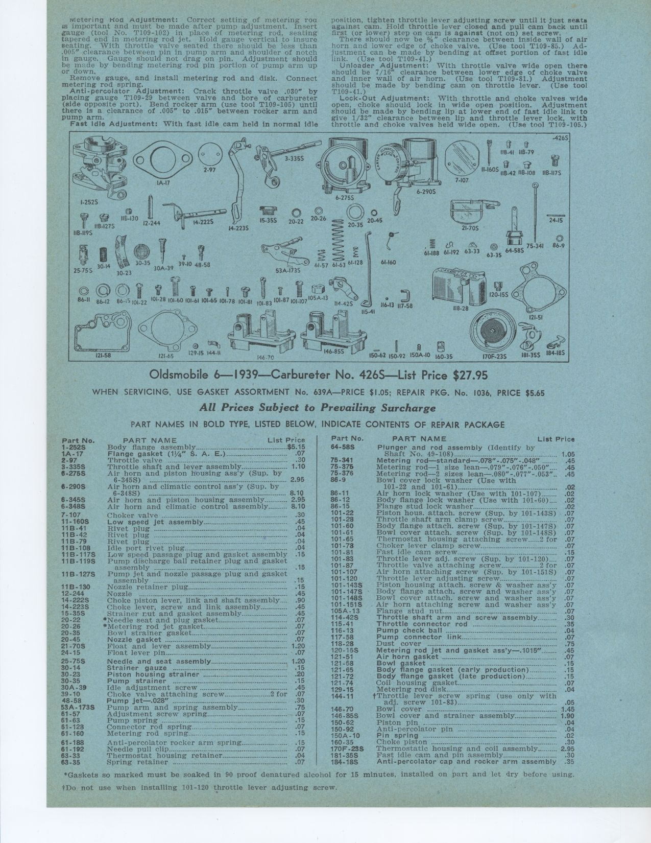
Oldsmobile 6—1939—Carbureter No. 4265—List Price $27.95
WHEN SERVICING, USE GASKET ASSORTMENT No. 639A—PRICE $1.05; REPAIR
PKG. No. 1036, PRICE $5.65
All Prices Subject to Prevailing Surcharge
PART NAMES IN BOLD TYPE, LISTED BELOW, INDICATE CONTENTS OF REPAIR PACKAGE
Part No. PART NAME List Price
1-252S Body flange assembly $5 15
1A-17 Flange gasket (1%4" S. A. E.) 07
2-97 Throttle valve 30
3-3355 Throttle shaft and lever assembly 1 10
6-275S Air horn and piston housing ass'y (Sup. by
6-345S) •--------- •-•--- ..... ...---- 2 95
6-290S Air horn and climatic control ass'y (Sup. by
6-348S) -----°- 8 10
6-345S Air horn and piston housing assembly 2 95
6-348S Air horn and climatic control assembly 8 10
7-107 Choker valve 30
11-160S Low speed jet assembly 45
11B-41 Rivet plug ---- 04
11B-42 Rivet plug 04
11B-79 Rivet plug 04
11B-108 Idle port rivet plug 04
11B-117S Low speed passage plug and gasket assembly .15 11B-119S Pump discharge
ball retainer plug and gasket
assembly ----------------------------- 15
11B-127S Pump jet and nozzle passage plug and gasket
assembly ---- ......................................°-- 15
11B-130 Nozzle retainer plug
15
12-244 Nozzle ---- ..............................................................
.45
14-222S Choke piston lever, link and shaft assembly__ 90
14-223S Choke lever, screw and link assembly 45
15-35S Strainer nut and gasket assembly 45
20-22 *Needle seat and plug gasket 07
20-26 *Metering rod jet gasket 07
20-35 Bowl strainer gasket 07
20-45 Nozzle gasket ....°°--°-°---°---° 07
21-70S Float and lever assembly 1 20
24-15 Float lever pin 07
25-75S Needle and seat assembly 1 20
30-14 Strainer gauze 15
30-23 Piston housing strainer 20
30-35 Pump strainer 15
30A-39 Idle adjustment screw 45
39-10 Choke valve attaching screw 2 for 07
48-58 Pump jet—.028" 30
53A-173S Pump arm and spring assembly 75 146-70
61-57 Adjustment screw spring 07 146-85S
61-63 Pump spring 15 150-62
61-128 Connector rod spring 07 150-92
61-160 Metering rod spring 15 150A-10
61.188 Anti-percolator rocker arm spring 15 160-35
61-192 Needle pull clip .07 170E-23S
63-33 Thermostat housing retainer 04 181-35S
63-35 Spring retainer 07 184-18S
*Gaskets so marked must be soaked in 90 proof denatured alcohol for 15 minutes,
installed on part and let dry before using.
tDo not use when installing 101-120 throttle lever adjusting screw.
PART NAME List Price
Plunger and rod assembly (Identify by
Shaft No. 49-108) 1 05
Metering rod—standard—.078"-.075"-.048" 45
Metering rod—1 size lean—.079"-.076"-.050" 45
Metering rod—2 sizes lean—.080"-.077"-.053" 45
Bowl cover lock washer (Use with
101-22 and 101-61) 02
Air horn lock washer (Use with 101-107) 02
Body flange lock washer (Use with 101-60) 02
Flange stud lock washer 02
Piston hous. attach. screw (Sup. by 101-143S) 07
Throttle shaft arm clamp screw 07
Body flange attach. screw (Sup. by 101-147S) 07
Bowl cover attach. screw (Sup. by 101-148S) 07
Thermostat housing attaching screw 2 for 07
Choker lever clamp screw 07
Fast idle cam screw 15
Throttle lever adj. screw (Sup. by 101-]20).... .07
Throttle valve attaching screw 2 for 07
Air horn attaching screw (Sup. by 101-151S) 07
Throttle lever adjusting screw 07
Piston housing attach. screw & washer ass'y 07
Body flange attach. screw and washer ass'y 07
Bowl cover attach. screw and washer ass'y 07
Air horn attaching screw and washer ass'y 07
Flange stud nut 07
Throttle shaft arm and screw assembly 30
Throttle connector rod 35
Pump check ball -04
Pump connector link 07
Dust cover 75
Metering rod jet and gasket ass'y—.1015" 45
Air horn gasket 07
Bowl gasket 15
Body flange gasket (early production) 15
Body fPange gasket (late production) 15
Coil housing gasket 07
Metering rod disk 04
tThrottle lever screw spring (use only with
adj. screw 101-83) 05
Bowl cover -- 1 45
Bowl cover and strainer assembly 1 90
Piston pin 04
Anti-percolator pin 04
Pin spring 02
Choke piston 30
Thermostatic housing and coil assembly 2 95
Fast idle cam and pin assembly 30
Anti-percolator cap and rocker arm assembly 35
|
