|
ANTI-PERCOLATOR ADJUSTMENT: Should be made after pump and metering
rod adjustments. Back out throttle lever adjusting screw so that throttle
valves seat in bores of carbureter. With throttle valve seated, insert .015" feeler
gauge (T109-72) between anti-percolator stem and lips on anti-percolator
arm. Then bend lips so that center of indicator lines are just flush with
top of anti-percolator plug. Care should be taken so there is an even adjustment
made on both anti-percolator lips.
UNLOADER ADJUSTMENT: With throttle wide open, distance between upper edge
of choke valve and inner wall of air horn should be 11/64". (Use gauge
T109-166.) Adjustment can be made by bending lip on fast idle connector link.
With throttle wide open, push choker valve open. Choke should lock within
5° of wide open position. If it does not lock, recheck unloader adjustment.
Closing the throttle will release choker valve. Choker trip lever is notched
out for this setting.
FAST IDLE ADJUSTMENT: Hold choker valve tightly closed and adjust fast idle
arm screw to give .023” to .028" opening between edge of throttle
valve and bore of carbureter, side opposite port. (Use gauge T109-114.)
STARTER SWITCH: Adjustment should be made with Carter tool No. T109-155S,
obtainable from your Carter distributor with complete instructions.
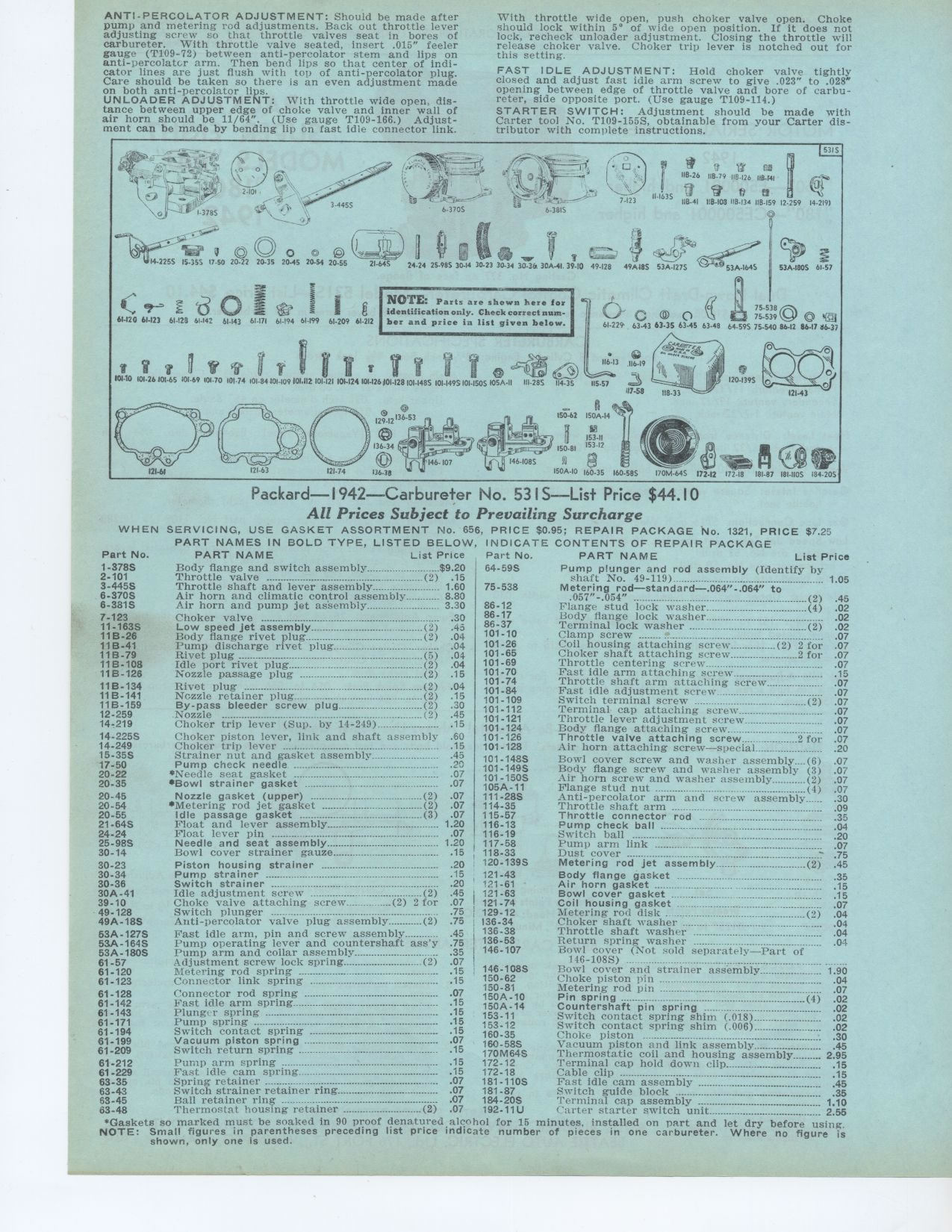
NOTE: Parts are shown here for identification only. Check correct number
and price in list given below.
Packard—I 942—Carbureter No. 53IS—List Price $44.10
All Prices Subject to Prevailing Surcharge
WHEN SERVICING, USE GASKET ASSORTMENT No. 656, PRICE $0.95; REPAIR PACKAGE
No. 1321, PRICE $7.25
PART NAMES IN BOLD TYPE, LISTED BELOW, INDICATE CONTENTS OF REPAIR PACKAGE
Part No. PART NAME List Price Part No. PART NAME List Price
Body flange and switch assembly $9 20 64-59S Pump plunger and rod assembly
(Identify by
Throttle valve ....----....--°° (2) 15 1 shaft No. 49-119)-- 1 05
Throttle shaft and lever assembly 1 60 75-538 Metering rod—standard—.064"-.064" to
Air horn and climatic control assembly 8 80 .057"-.054" (2)
Air horn and pump jet assembly 3 30 86-12 Flange stud lock washer._. (4)
86-17 Body flange lock washer
86-37 Terminal lock washer (2)
101-10 Clamp screw ...-°----
101-26 Coil housing attaching screw (2) 2 for
101-65 Choker shaft attaching screw 2 for
101-69 Throttle centering screw
101-70 Fast idle arm attaching screw
101-74 Throttle shaft arm attaching screw 101-84 Fast idle adjustment screw
__
101-109 Switch terminal screw (2)
101-112 Terminal cap attaching screw
101-121 Throttle lever adjustment screw
101-124 Body flange attaching screw
101-126 Throttle valve attaching screw 2 for
101-128 Air horn attaching screw—special
Choker valve
Low speed jet assembly (2)
Body flange rivet plug (2)
Pump discharge rivet plug
Rivet plug ...... ... (5)
Idle port rivet plug (2)
Nozzle passage plug (2)
Rivet plug (2)
Nozzle retainer plug (2)
By-pass bleeder screw plug (2)
Nozzle ............
(2) Choker trip lever (Sup. by 14-249)
Choker piston lever, link and shaft assembly 60
Choker trip lever 15
Strainer nut and gasket assembly 45
Pump check needle 20
*Needle seat gasket 07
*Bowl strainer gasket _. 07
Nozzle gasket (upper) (2) 07
*Metering rod jet gasket (2) 07
Idle passage gasket (3) 07
Float and lever assembly.... . 1 20
Float lever pin .07
Needle and seat assembly 1 20
Bowl cover strainer gauze 15
Piston housing strainer 20
Pump strainer 15 121-43 Body flange gasket 35
Switch strainer 20 121-61 Air horn gasket
15
Idle adjustment screw (2) 45 121.63 Bowl cover gasket 1
Choke valve attaching screw! - - (2) 2 for 07 121-74 Coil housing gasket 07
Switch plunger 75 129-12 Metering rod disk . (2)
Anti-percolator valve plug assembly (2) 75 136-34 Choker shaft washer .04 .04
Fast idle arm, pin and screw assembly _ .45 136.38 Throttle shaft washer 04
Pump operating lever and countershaft ass'y 75 136-53 Return spring washer
04
Pump arm and collar assembly 35 146-107 Bowl cover (Not sold separately—Part
of
Adjustment screw lock spring (2) 07 146-1085) ---- -------
rod spring 15 146-108S Bowl cover and strainer assembly 1 90
Connector link spring 15 150-62 Choke piston pin 04
150-81 Metering rod pin -07
61-128 Connector rod spring 07 150A-10 Pin spring
61-142 Fast idle arm spring ° ° 15 15 Countershaft spring 02
153-11 Switch t pin ng .___(._1_ 02
61-143 Plunger spring 15 153-11 Switch contact spring shim (.018) 02
61-171 Pump spring 15 153-12 Switch contact spring shim (.006) 02
61-194 Switch contact spring 15 160-35 Choke piston
30
61-199 Vacuum piston spring 07 160-58S
61-209 Switch return spring 15 61-212
61-229 63-35 63-43 63-45 63-48
101-148S Bowl cover screw and washer assembly (6) 07
101-149S Body flange screw and washer assembly (3) 07
101.1505 Air horn screw and washer assembly (2) 07
105A-11 Flange stud nut (4) 07
111-28S Anti-percolator arm and screw assembly_ _. .30
114-35 Throttle shaft arm 09
115-57 Throttle connector rod 35
116-13 Pump check ball 04
116-19 Switch ball 20
117-58 Pump arm link 07
118-33 Dust cover -°.° ....... ..............' 75
120-139S Metering rod jet assembly (2) 45
Vacuum piston and link assembly 45
170M64S Thermostatic coil and housing assembly 2 95
Pump arm spring 15 172-12 Terminal cap hold down clip 15
Fast idle cam spring 15 172-18 Cable clip --------------... °° ...
........ .... .15
Spring retainer 07 181-110S Fast idle cam assembly 45
Switch strainer retainer ring 07 181-87 Switch guide block 35
Ball retainer ring 07 184-20S Terminal cap assembly ...°° 1 10
Thermostat housing retainer (2) 07 192-11U Carter starter switch unit 2 56
'Gaskets so marked must be soaked in 90 proof denatm•ed alcohol for 15
minutes, installed on part and let dry before using. NOTE: Small figures in
parentheses preceding list price indicate number of pieces in one carbureter.
Where no figure is shown, only one is used.
|