|
CARTER CARBURETOR CORPORATION, Si. LOUIS, MO., U. S. A.
Form 6486A—Canadian
PACKARD 530S
March, 1942
Reprinted January, 1945
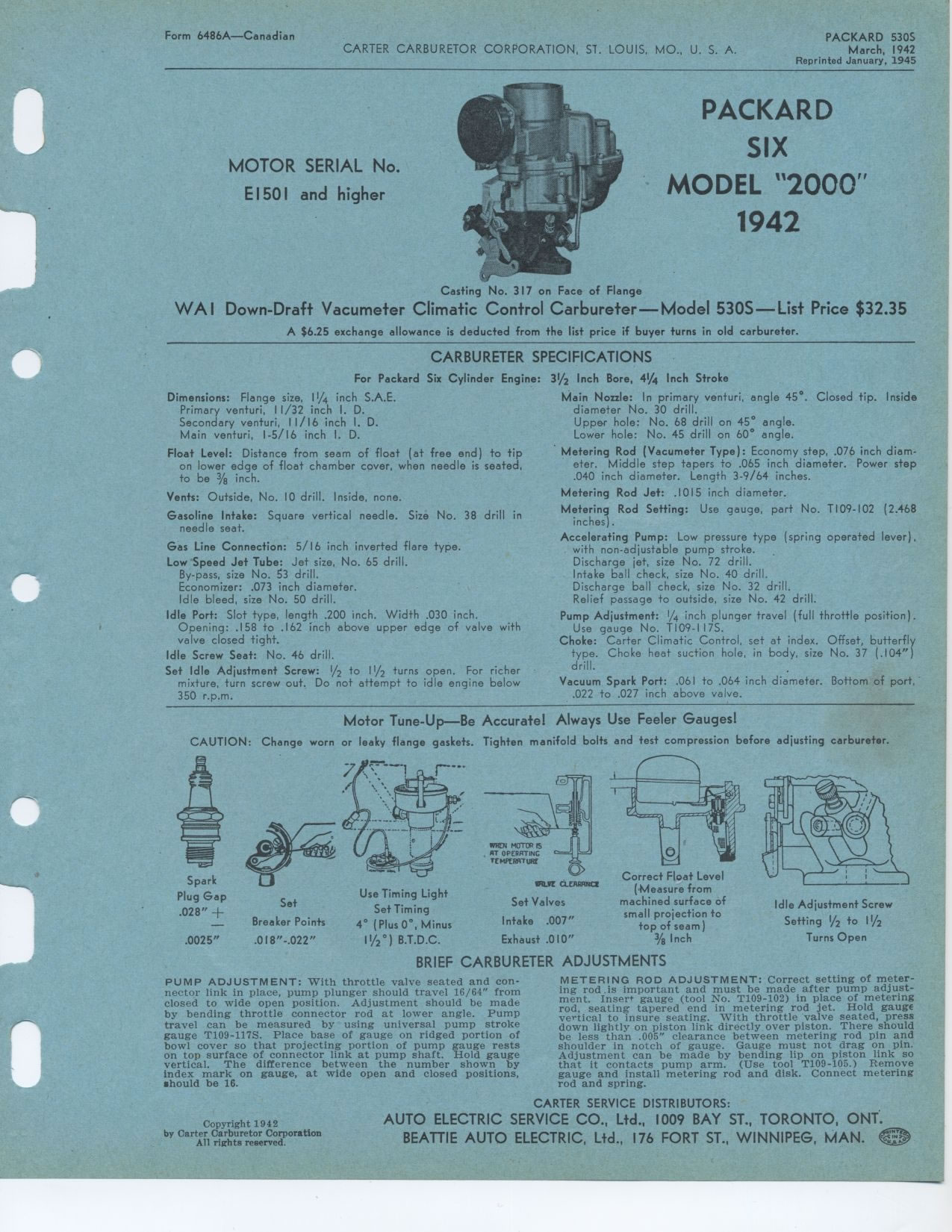
PACKARD SIX MODEL 2000 1942
Casting No. 317 on Face of Flange
WAI Down-Draft Vacumeter Climatic Control Carbureter—Model 530S—List
Price $32.35
A $6.25 exchange allowance is deducted from the list price if buyer turns
in old carbureter.
CAR.BURETER SPECIFICATIONS
MOTOR SERIAL No.
E1501 and higher
For Packard Six Cylinder Engine:
Dimensions: Flange size, 1¼ inch S.A.E.
I. D. D.
I.
Primary venturi, 11/32 inch
Secondary venturi, 11/16 inch
Main venturi, 1-5/16 inch I. D.
Float Level: Distance from seam of float (at free end) to tip on lower edge
of float chamber cover, when needle is seated, to be 3/8 inch.
Vents: Outside, No. 10 drill. Inside, none.
Gasoline Intake: Square vertical needle. Size No. 38 drill in needle seat.
Gas Line Connection: 5/16 inch inverted flare type.
Low Speed Jet Tube: Jet size, No. 65 drill.
By-pass, size No. 53 drill.
Economizer: .073 inch diameter.
Idle bleed, size No. 50 drill.
Idle Port: Slot type, length .200 inch. Width .030 inch. Opening: .158 to .162
inch above upper edge of valve with valve closed tight.
Idle Screw Seat: No. 46 drill.
Set Idle Adjustment Screw: 1/2 to 11/2 turns open. For richer mixture, turn
screw out. Do not attempt to idle engine below 350 r.p.m.
31/2 Inch Bore, 4¼ Inch Stroke
Main Nozzle: In primary venturi, angle 45°. Closed tip. Inside diameter
No. 30 drill.
Upper hole: No. 68 drill on 45° angle. Lower hole: No. 45 drill on 60° angle.
Metering Rod (Vacumeter Type): Economy step, .076 inch diameter. Middle step
tapers to .065 inch diameter. Power step .040 inch diameter. Length 3-9/64
inches.
Metering Rod Jet: .1015 inch diameter.
Metering Rod Setting: Use gauge, part No. T109-102 (2.468 inches).
Accelerating Pump: Low pressure type (spring operated lever), with non-adjustable
pump stroke.
Discharge jet, size No. 72 drill.
Intake ball check, size No. 40 drill.
Discharge ball check, size No. 32 drill.
Relief passage to outside, size No. 42 drill.
Pump Adjustment: 1/4 inch plunger travel (full throttle position). Use gauge
No. T109-117S.
Choke: Carter Climatic Control, set at index. Offset, butterfly type. Choke
heat suction hole, in body, size No. 37 (.104") drill.
Vacuum Spark Port: .061 to .064 inch diameter. Bottom of port, .022 to .027
inch above valve.
Motor Tune-Up—Be Accurate! Always Use Feeler Gauges!
CAUTION: Change worn or leaky flange gaskets. Tighten manifold bolts and test
compression before adjusting carbureter.
BRIEF CARBURETER ADJUSTMENTS
PUMP ADJUSTMENT: With throttle valve seated and connector link in place, pump
plunger should travel 16/64" from closed to wide open position. Adjustment
should be made by bending throttle connector rod at lower angle. Pump travel
can be measured by using universal pump stroke gauge T109-117S. Place base
of gauge on ridged portion of bowl cover so that projecting portion of pump
gauge rests on top surface of connector link at pump shaft. Hold gauge vertical.
The difference between the number shown by index mark on gauge, at wide open
and closed positions, should be 16.
Copyright 1942
by Carter Carburetor Corporation
All rights reserved.
Spark Plug Gap .028" +
.0025"
Set Breaker Points .018"-.022"
Use Timing Light
Set Timing
4° (Plus 0°, Minus
11/2 °) B.T.D.C.
slum ^:iremr;s Set Valves Intake .007" Exhaust .010"
Correct Float Level
(Measure from
machined surface of
small projection to
top of seam)
% Inch
Idle Adjustment Screw Setting 1/2 to I1/2 Turns Open
METERING ROD ADJUSTMENT: Correct setting of metering rod.is important and
must be made after pump adjustment. Insert gauge (tool No. T109-102) in place
of metering rod, seating tapered end in metering rod jet. Hold gauge vertical
to insure seating. With throttle valve seated, press down lightly on piston
link directly over piston. There should be less than .005" clearance
between metering rod pin and shoulder in notch of gauge. Gauge must not drag
on pin. Adjustment can be made by bending lip on piston link so that it contacts
pump arm. (Use tool T109-105.) Remove gauge and install metering rod and
disk. Connect metering rod and spring.
CARTER SERVICE DISTRIBUTORS:
|