|
ANTI-PERCOLATOR ADJUSTMENT: Crack throttle valve .030" by
placing gauge T109-29 between valve and bore of carbureter (side opposite
port). Bend rocker arm (use tool T109-105) until there is a clearance of
.005" to .015" between rocker arm and pump arm.
FAST IDLE ADJUSTMENT: With fast idle cam held in normal idle position, tighten
throttle lever adjusting screw until it just seats against cam. Hold throttle
lever closed and pull cam back until first (or lower) step on cam is against
(not on) set screw.
There should now be %" clearance between inside wall of air horn and
lower edge of choke valve. (Use tool T109-85.) Adjustment can be made by
bending at offset portion of fast idle link. (Use tool T109-41.)
UNLOADER ADJUSTMENT: With throttle valve wide open there should be 7/16" clearance
between lower edge of choke valve and inner wall of air horn. (Use tool T109-81.)
Adjustment should be made by bending cam on throttle lever. (Use tool T109-41.)
LOCK-OUT ADJUSTMENT: With throttle and choke valves wide open, choke should
lock in wide open position. Adjustment should be made by bending lip at lower
end of fast idle link to give 1/32" clearance between lip and throttle
lever lock, with throttle and choke valves held wide open. (Use tool T109-105.)
STARTER SWITCH ADJUSTMENT: Adjustment should be made with Carter tool T109-155S,
obtainable from your Carter distributor with complete instructions.
t e
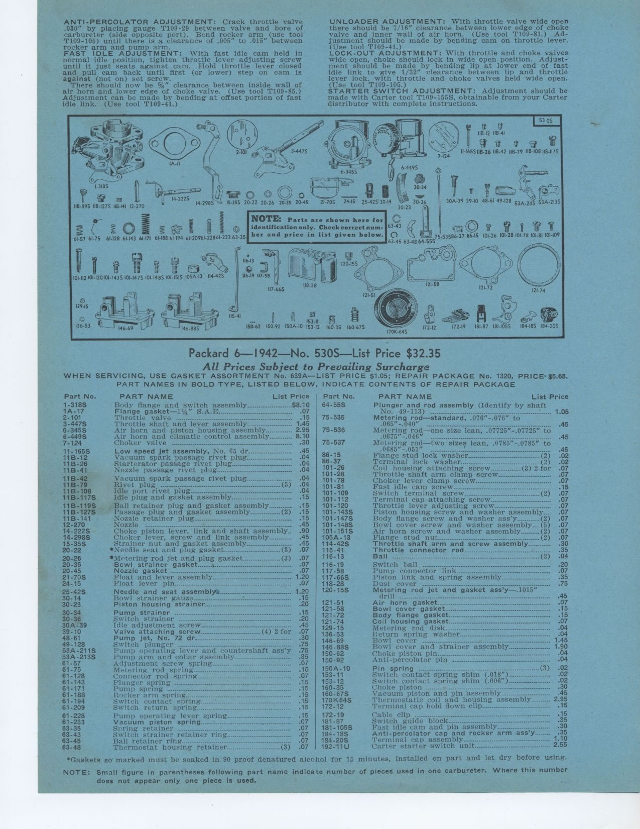
NOTE: Parts are shown here for identification only. Check correct number
and price in list given below.
Packard 6—1942—No. 530S—List Price $32.35
All Prices Subject to Prevailing Surcharge
WHEN SERVICING, USE GASKET ASSORTMENT No. 639A—LIST PRICE $1.05; REPAIR
PACKAGE No. 1320, PRICE $5.65.
PART NAMES IN BOLD TYPE, LISTED BELOW, INDICATE CONTENTS OF REPAIR PACKAGE
Part No. 1-318S 1A-17 2-101 3-447S 6-345S 6-449S 7-124 11-165S 11B-12 11B-26
11B-41
11B-42 11 B-79 11B-108 11B-117S
11B-119S 11B-127S 11B-141 12-270 14-2225 14-298S 15-35S 20-22
20-26 20-35 20-45 21-70S 24-15
25-42S 30-14 30-23
30-34 30-36 30A-39 39-10 48-61 49-128 53A-211S 53A-213S 61-57 61-75 61-128
61-143 61.171 61-188 61-194 61-209
61-228 61-233 63-35 83-43 63.45 63-48
PART NAME List Price
Body flange and switch assembly $8.10
Flange gasket—11/a" S.A.E 07
Throttle valve 15
Throttle shaft and lever assembly 1.45
Air horn and piston housing assembly 2.95
Air horn and climatic control assembly 8.10
Choker valve °°°° 30
Low speed jet assembly, No. 65 dr
Vacuum spark passage rivet plug
Starterator passage rivet plug
Nozzle passage rivet plug
Vacuum spark passage rivet plug
Rivet plug ... (5)
Idle port rivet plug
Idle plug and gasket assembly
Ball retainer plug and gasket assembly
Passage plug and gasket assembly (2)
Nozzle retainer plug
Nozzle ° ................................................
Choke piston lever, link and shaft assembly
Choker lever, screw and link assembly
Strainer nut and gasket assembly
*Needle seat and plug gasket (3)
*Metering rod jet and plug gasket (3)
Bcwl strainer gasket
Nozzle gasket -----° 07
Float and lever assembly 1.20
Float lever pin 07
Needle and seat assembly. ..
Bowl strainer gauze
Piston housing strainer
Pump strainer _ .
Switch strainer
Idle adjustment screw
Valve attaching screw (4) 2 for
Pump jet, No. 72 dr
Switch plunger
Pump operating lever and countershaft ass'y
Pump arm and collar assembly
Adjustment screw spring
Metering rod spring
Connector rod spring
Plunger spring -----°---
Pump spring
Rocker arm spring
Switch contact spring
Switch return spring
Pump operating lever spring
Vacuum piston spring
Spring retainer
Switch strainer retainer ring
Ball retainer ring .......................................................
Thermostat housing retainer (3)
Part No. 64-55S
PART NAME List Price
Plunger and rod assembly (Identify by shaft
No. 49-113) 1 05
Metering rod—standard, .076"-.076" to
.065"-.040" ...° ° °--°-- 45
Met ring rod—one size lean, .07725"-.07725" to
.0675"-.046" .---.... ° 45
Metering rod—two sizes lean, .0785"-.0785" to
.0685"-.051" 45
Flange stud lock washer (2) 02
Terminal lock washer (2) 02
Coil housing attaching screw (3) 2 for 07
Throttle shaft arm clamp screw 07
Choker lever clamp screw 07
Fast idle cam screw 15
Switch terminal screw (2) 07
Terminal cap attaching screw 07
Throttle lever adjusting screw 07
Piston housing screw and washer assembly 07
Body flange screw and washer ass'y (2) 07
Bowl cover screw and washer assembly (5) 07
Air horn screw and washer assembly (2) 07
Flange stud nut (2) 07
Throttle shaft arm and screw assembly 30
Throttle connector rod
5 Ball -° ----------°-- ° (2) 04
Switch ball -°- 20
Pump connector link 07
Piston link and spring assembly 35
Dust cover --- .................................................... .75
Metering rod jet and gasket ass'y—.1015"
drill 45
Air horn gasket 07
Bowl cover gasket 15
Body flange gasket 15
Coil housing gasket 07
Metering rod disk 04
I:eturn spring washer 04
Bowl cover 1 45
Bowl cover and strainer assembly 1 90
Choke piston pin ............................................................
.04
Anti-percolator pin 04
Pin spring (3) 02
Switch contact spring shim (.018") 02
Switch contact spring shim (.006") 02
Choke piston 30
Vacuum piston and pin assembly 45
Thermostatic coil and housing assembly 2 95
Terminal cap hold down clip 15
Cable clip - .15
Switch guide block 35
Fast idle cam and pin assembly 30
Anti-percolator cap and rocker arm ass'y 35
Terminal can assembly 1 10
Carter starter switch unit 2 55
minutes, installed on part and let dry before using.
*Gaskets so' marked must be soaked in 90 proof denatured alcohol for 15
NOTE: Small figure in parentheses following part name indicate number of pieces
used in one carbureter. Where this number does not appear only one piece is
used.
|