|
CARTER CARBURETOR CORPORATION, ST. LOUIS, MO., U. S. A.
Form 6483D—Canadian
STUDEBAKER 5145
August, 1941
Reprinted August, 1947
MOTOR SERIAL NUMBERS
3M-00I and higher
CAR SERIAL NUMBERS
MI6-001 and higher
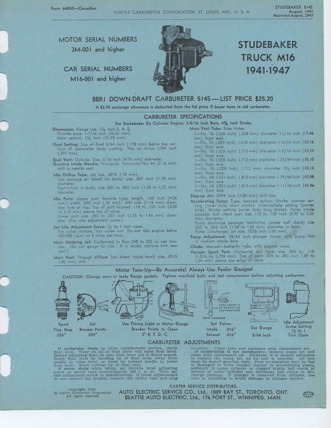
STUDEBAKER TRUCK M16 1941 1947
BBRI DOWN 'DRAFT CARBURETER 514S— LIST PRICE $25.20
A $3.75 exchange allowance is deducted from the list price if buyer turns
in old carbureter.
CARBURETER SPECIFICATIONS
Cylinder Engine: 3-5/16 Inch Bore, 4% Inch Stroke
Main Vent Tube: Side Holes: I—No. 76 (.020 inch) (.508 mm) from end.
I—No. 73 (.024 inch) (.610 mm) from end.
For Studebaker Six
Dimensions: Flange size, 11/4 inch S. A. E. Throttle bore, 1-7/16 inch (36.51
mm). Main venturi, 11/4 inch (31.75 mm).
Float Setting: Top of float 5/64 inch (1.98 mm) below top surface of carbureter
body casting. Plus or minus 1/64 inch (.397 mm).
Bowl Vent: Outside. Size, 3/16 inch (4.76 mm) diameter. Gasoline Intake Needle:
Triangular, horizontal No. 44 (2.18 drill in needle seat.
Idle Orifice Tube: Jet size, .0276 (.70 mm).
Idle passage air bleed (in body) size, .067 inch (1.70 diameter.
Restriction, in body, size .051 to .052 inch (1.30 to 1.32 diameter.
Idle Ports: Upper port, keyhole type, length, .160 inch (4.06
mm) ; width, .030 inch (.76 mm) ; .045 inch (1.14 mm) diam-
eter hole at top. Top of port located .118 to .122 inch (3.00
to 3.10 mm) above top of valve.
Lower port size, .053 to .057 inch (1.35 to 1.45 mm) diameter. (For idle
adjustment screw.)
Set Idle Adjustment Screw: 1/2 to 1 turn open.
For richer mixture, turn screw out. Do not idle engine below 400-450 r.p.m.
or 6 miles per hour.
Main Metering Jet: Calibrated to flow 248 to 252 cc per minute. (Do not gauge
for size. If in doubt, replace with new part.)
Main Vent: Through diffuser (air bleed inside bowl) size, .0315 (.80 mm)
drill.
I—No. 70 (.028 inch) (.712 mm) diameter 1-5/16 inch mm) from end.
I—No. 70 (.028 inch) (.712 mm) diameter 1-27/64 inch mm) from end.
I—No. 70 (.028 inch) (.712 mm) diameter 11/2 inch mm) from end.
I—No. 68 (.031 inch) (.812 mm) diameter 1-39/64 inch mm) from end.
I—No. 68 (.031 inch) (.812 mm) diameter 1-11/16 inch mm) from end.
Step-up Jet: .0394 inch (1.00 mm) drill size.
Accelerating Pump: Type, delayed action. Stroke, summer setting (inner hole,
short stroke). Intermediate setting (center hole). Winter setting (outer
hole, long stroke). Pump intake passage, ball check seat, size .115 to .120
inch (2.92 to 3.05 mm) diameter.
Pump discharge passage; restriction (under ball check) size .062 to .065
inch (1.58 to 1.65 mm) diameter in body.
mm)
mm) mm)
mm) diameter 11/16 inch (17.46
mm) diameter 1-3/16 inch (30.16
(33.34
(38.10
(38.10
(40.88
(42.86
Pump (discharge) jet size, .0236 inch (.60 mm).
Pump Adjustment: 38/64 inch plunger travel, with pump link in medium stroke
hole.
Choke: Manual—butterfly type, with poppet valve.
Vacuum Spark Port: Horizontal slot type; size, .040 by .110 (1.016 by 2.794
mm). Top of port: .035 to .041 inch (.89 to 1.04 mm) above top edge of valve.
Motor Tune-Up—Be Accurate! Always Use Feeler Gauges!
CAUTION: Change worn or leaky flange gaskets. Tighten manifold bolts and
test compression before adjusting carbureter.
CARBURETER ADJUSTMENTS
Spark Set
Plug Gap Breaker Points
.025" .020"'tr=y
Use Timing Light or Motor Gauge
Breaker Points to Open
2° B. T. D. C.
VALVE CLEARANCE
Set Valves
Intake .016"
Exhaust .016"Idle Adjustment
Screw Setting
I/2 to I
Turn Open
If carbureter loads up after considerable service, check float level. Wear
on lip of float lever will raise float level. Before adjusting float, be
sure float lever pin is firmly seated. Reset float level by bending lip of
float lever away from needle to raise level, or bend lip toward needle to
lower float level. Bend vertical lip of float only.
If motor stalls while idling, set throttle lever adjusting screw so motor
runs approximately 400 r. p. m. Then set idle adjustment screvh to specifications.
If these adjustments do not correct the trouble, remove idle orifice tube
and plugassembly. Clean tube and passages with compressed air.
If acceleration is not satisfactory, remove pump jet and clean with compressed
air. However, it is usually advisable to replace the pump jet, as its cost
is nominal. All jets must be seated gasoline tight. Poor acceleration may
be due to damaged or worn plunger leather in accelerating pump, sediment
in pump cylinder or clogged intake ball check at bottom of pump cylinder
and discharge ball check in discharge passage. If plunger is removed from
cylinder, use care in installing to avoid damage to plunger leather.
Copyright 1941
by Carter Carburetor Corporation
All rights reserved
CARTER SERVICE DISTRIBUTORS:
AUTO ELECTRIC SERVICE CO., Ltd., 1009 BAY ST., TORONTO, ONT.
BEATTIE AUTO ELECTRIC, Ltd., 176 FORT ST., WINNIPEG, MAN.
|