|
CARTER CARBURETOR CORPORATION, ST. LOUIS, MO., U. S. A.
Correct air fuel ratio is provided by a "balance tube" in the air
horn. The balance tube should be checked each time the carbureter is serviced
to see that the passage is open. The object of a balanced carbureter is to
provide a constant air fuel ratio regardless of type, size or condition of
air cleaner. Should the cleaner become clogged, the capacity will he reduced
but the air-fuel mixture ratio will not be changed.
Excessive richness above 50 miles per hour may be caused by a clogged main
vent tube. After removal of rivet plug beneath float bowl with tool No. T109-42,
main vent tube can be removed and a new tube inserted with tool No. T109-70.
Care must be exercised in inserting new tube which must seat tightly. Use
new rivet to complete the installation.
Pump adjustment: Remove air horn assembly, back out throttle adjustment screw,
and place pump operating link in center hole of throttle shaft arm. Adjustment
can be made by bending horizontal portion of pump connector link, so that
top of pump plunger shaft contacts lip of indicator onpump stroke gauge T109-117S.
Correct travel is 38/64".
Pump stroke adjustable for high or low temperature. Set to longest stroke
for cold weather, shorter stroke for hot weather driving.
Maximum economy and performance are secured only when breaker points, spark
plugs, valves and motor timing are set to manufacturer's specifications.
After motor is properly tuned, the following should also be done to insure
satisfactory performance and economy:
(a) Float level must be set as above.
(b) Step-up rod in step-up jet must seat and move freely. When reassembling,
jet must be screwed in tight against seat.
(c) Step-up piston in body casting should not bind and must be free of dirt.
(d) Main metering jet can be replaced with leaner than standard metering
jets for altitude.
Caution. Do not attempt to gauge metering jets with drills. These jets have
been flow-tested to insure correct fuel flow.
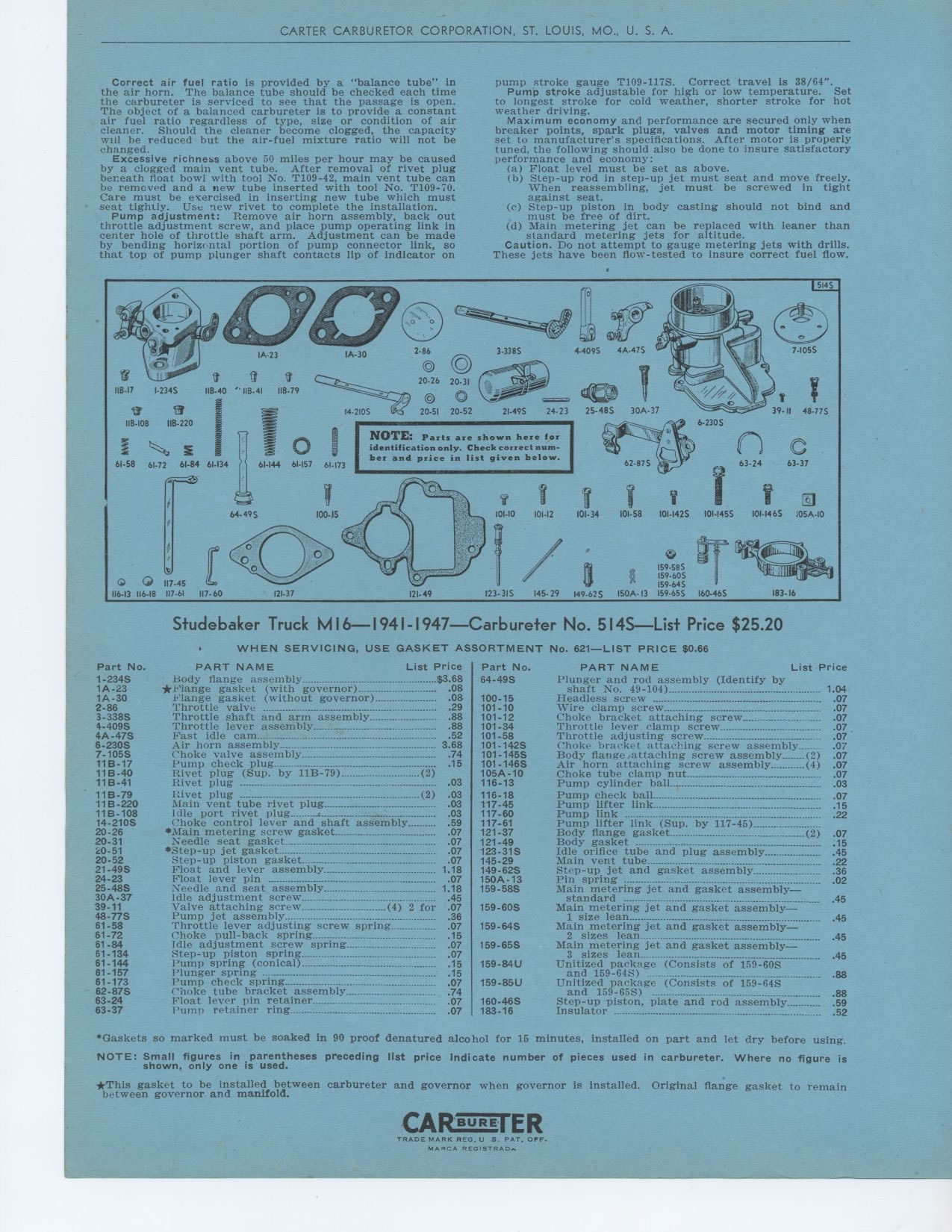
Studebaker Truck M16 — 1941 1947 — Carbureter No. 514S
No.
Plunger and rod assembly (Identify by
shaft No. 49-104) Headless screw °-°---_.
Wire clamp screw---
Choke bracket attaching screw
Throttle lever clamp screw
Throttle adjusting screw
...
Choke braeked- attaching screw assembly
Body flange attaching screw assembly (2)
Air horn attaching screw assembly (4)
Choke tube clamp nut
Pump cylinder ball
Pump check ball
Pump lifter link
Pump link °
Pump lifter link (Sup. by 117-45)
Body flange gasket (2)
Body gasket ---
Idle orifice tube and plug assembly
Main vent tube
Step-up jet and gasket assembly
Pin spring -_--
Main metering jet and gasket assembly
standard ---°---°-° ----
Main metering jet and gasket assembly
1 size lean
Main metering jet and gasket assembly
2 sizes lean
Main metering jet and gasket assembly
3 sizes lean__
Unitized package (Consists of 159-60S
and 159-64S)
Unitized package (Consists of 159-64S
and 159-65S)
Step-up piston, plate and rod assembly
Insulator
'Gaskets so marked must be soaked in 90 proof denatured alcohol for 15
minutes, installed on part and let dry before using.
NOTE: Small figures in parentheses preceding Ilst price Indicate number
of pieces used in carbureter. Where no figure is shown, only one is used.
*This gasket to be installed between carbureter and governor when governor
is installed. Original flange gasket to remain between governor and manifold.
118-17 1-2345 118-40 ''I113-41 118.79
F3 Et
I18-108 IIB-220
E
61.58 61.72 61.84 61-134
®1
61.144 61.157 61-173
NOTE: Parts are shown here for identification only. Check correct number and
price in list given below.
64-49$
O ® 117-45
116-13 116-18 117.61 117- 60
183.16
123-31S
121-37
121- 49
15985 - I59-60S 159-64S
145-29 149-62S 150A-13 159-65$ 160-46$
WHEN SERVICING, USE GASKET ASSORTMENT
Part No. PART NAME List Price
1-234S Body flange assembly $3 68
1A-23 *Flange gasket (with governor) 08
1A-30 Flange gasket (without governor) 08
2-86
3-338S
4-409S 4A-47S 6-230S 7-105S 11B-17
11 B-40 11B-41 11B-79 11B-220 11B-108 14-210S
20-26 20-31 20-51 20-52 21-49S
24-23 25-48S 30A-37
39-11 48-77S
61-58 61-72 61-84 61-134 61-144 61.157 61-173 62-87S
63-24 63-37
'1 hrottle valve - 29
Throttle shaft and arm assembly 88
Throttle lever assembly 88
Fast idle cam 52
Air horn assembly--_ 3 68
Choke valve assembly 74
Pump check plug 15
Rivet plug (Sup- by 11B-79) (2)
Rivet plug 03
Rivet plug -(2) 03
Main vent tube rivet plug 03
Idle port rivet plug 03
Choke control lever and shaft assembly 59
*Main metering screw gasket 07
Needle seat gasket 07
*Step-up jet gasket 07
Step-up piston gasket 07
Float and lever assembly 1 18
Float lever pin 07
Needle and seat assembly 1 18
Idle adjustment screw 45
Valve attaching screw (4) 2 for 07
Pump jet assembly 36
Throttle lever adjusting screw spring 07
Choke pull-back spring 15
Idle adjustment screw spring 07
Step-up piston spring 07
Pump spring (conical) 15
Plunger spring °°°--- 15
Pump check spring 07
Choke tube bracket assembly 74
Float lever pin retainer 07
I'ump retainer ring 07
Part No. 64-49S160-46S 183-16
621—LIST PRICE $0.66
PART NAME List Price
|