|
CARTER CARBURETOR CORPORATION, ST. LOUIS, MO., U. S. A.
Form 6458B—Canadian
STUDEBAKER 496S
November, 1940
Reprinted January, 1945
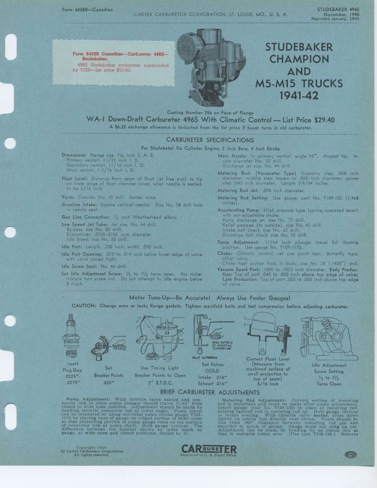
STUDEBAKER CHAMPION AND M5 M15 TRUCKS 1941 1942
Casting Number 356 on Face of Flange
WA- I Down-Draft Carbureter 496S With Climatic Control — List Price
$29.40
A $6.25 exchange allowance is deducted from the list price if buyer turns
in old carbureter.
CARBURETER SPECIFICATIONS
For Studebaker Six Cylinder Engine, 3 Inch Bore, 4 Inch Stroke
Form 6458B Canadian—Carbureter 496S—Studebaker.
496S Studebaker carbureter superseded by 532S—list price $33.60.
Dimensions: Flange size, 1¼ inch S. A. E. Primary venturi, 11/32 inch
I. D.
Secondary venturi, 11/16 inch I. D. Main venturi, 1-3/16 inch I. D.
Float Level: Distance from seam of float (at free end) to tip on lower
edge of float chamber cover, when. needle is seated, to be 5/16 inch.
Vents: Outside. No. 10 drill. Inside, none.
Gasoline Intake: Square vertical needle. Size No. 38 drill hole in needle
seat.
Gas Line Connection: 1/4 inch Weatherhead elbow.
Low Speed Jet Tube: Jet size, No. 64 drill. By-pass, size No. 50 drill.
Economizer, .0755-.0765 inch diameter. Idle bleed, size No. 50 drill.
Idle Port: Length, .200 inch; width, .030 inch.
Idle Port Opening: .010 to .014 inch below lower edge of valve with valve
closed tight.
Idle Screw Seat: No. 46 drill.
Set Idle Adjustment Screw: 1/2 to 11/2 turns open. For richer mixture
turn screw out. Do not attempt to idle engine below 8 m.p.h.
Main Nozzle: In primary venturi, angle 45°. Angled tip. In-side diameter
No. 30 drill.
Discharge jet size. No. 44 drill.
Metering Rod: (Vacumeter Type) Economy step, .068 inch diameter; middle
step tapers to .060 inch diameter; power step .043 inch diameter. Length
3-9/64 inches.
Metering Rod Jet: .098 inch diameter.
Metering Rod Setting: Use gauge, part No. TI09-102 (2.468 inches).
Accelerating Pump: High pressure type (spring operated lever) with non-adjustable
stroke.
Pump discharge jet, size No. 72 drill.
Relief passage (to outside), size No. 42 drill.
Intake ball check, size No. 62 drill.
Discharge ball check, size No. 32 drill.
Pump Adjustment: 11/64 inch plunger travel full throttle position. Use
gauge No. T109-II7S.
Choke: Climatic control, set one point lean. Butterfly type, offset valve.
Choke heat suction hole, in body, size No. 28 (.1405") drill.
Vacuum Spark Port: .1005 to .1025 inch diameter. Early Production: Top
of port .045 to .050 inch above top edge of valve; Late Production: Top
of port .055 td .060 inch above top edge of valve.
Motor Tune-Up—Be Accurate! Always Use Feeler Gauges!
CAUTION: Change worn or leaky flange gaskets. Tighten manifold bolts
and test compression before adjusting carbureter.
Spark Plug Gap .0225"-.0275"
BRIEF CARBURETER ADJUSTMENTS
Set Use Timing Light
Breaker Points Breaker Points to Open
.020" 2° B.T.D.C.
VALVE CLCAMCE
Set Valves
COLD
Intake .016"
Exhaust .016"
Correct Float Level
(Measure from
machined surface of
small projection to
top of seam)
5/16 Inch
Idle Adjustment
Screw Setting
/2 to 11/2
Turns Open
Pump Adjustment: With throttle valve seated and connector link in place
pump plunger should travel 11/64` from closed to wide open position.
Adjustment should be made by bending throttle connector rod at lower
angle. Pump travel can be measured by using universal pump stroke gauge
T109-117S by placing base of gauge on ridged portion of bowl cover so
that projecting portion of pump gauge rests on top surface of connector
link at pump shaft. Hold gauge vertical. The difference between the number
shown by index mark on gauge, at wide open and closed positions, should
be 11.
Metering Rod Adjustment: Correct setting of metering rod is important
and must be made after pump adjustment Insert gauge (tool T109-102) in
place of metering rod, seating tapered end in metering rod jet Hold gauge
vertical to insure seating. With throttle valve seated, press down lightly
on piston link directly over piston. There should he less than .005" clearance
between metering rod pin and shoulder in notch of gauge. Gauge must not drag
on pin Adjustment can be made by bending lip on piston link so that it contacts
pump arm. (Use tool T109-105.) Remove
Copyright 1940 -
by Carter Carburetor Corporation All rights reserved.
CA BORE ER
Registered in C. S. Patent Ofrice
|