|
CARTER CARBURETOR CORPORATION, ST. LOUIS, MO., U. S. A.
Form 64006—Canadian
STUDEBAKER 468$
December, 1939
Reprinted December, 1944
MOTOR SERIAL NUMBERS
WITH OVERDRIVE 39183 and higher
WITHOUT OVERDRIVE
39319 and higher
STUDEBAKER CHAMPION MODEL 2G 1940
Casting No. 229 on face of flange
W-O DOWN-DRAFT CARBURETER 468S—LIST PRICE $ 17.85
A $2.50 exchange allowance is deducted from the list price if buyer turns
in old carbureter.
CARBURETER SPECIFICATIONS
For Studebaker 468S—6 Cylinder
Dimensions: Flange size, 11/4 inch S. A. E. Primary venturi, 11/32 inch I.
D. Main venturi. 1.0 inch I. D.
Float Setting: Distance from float (at free end) to float chamber cover to
be 1/4 inch when needle is seated.
Vents: Outside, No. 10 drill size. Inside, none. Idle well to bowl fuel chamber
No. 30 drill.
Gasoline Intake: Square vertical needle. No. 48 drill size in needle seat.
Gasoline Line Connection: 1/4 inch weatherhead elbow.
Low Speed Jet Tube: Jet size, No. '69 drill. Idle well jet, No. 56 drill.
By-pass in body, .052 inch diameter.
Economizer in body, .046-.047 inch diameter.
Idle bleed, size No. 45 drill.
Idle Port: Length, .160 inch. Width, .030 inch.
Idle Port Opening: .028 to .032 inch (below lower edge of valve) with valve
tight closed.
Idle Screw Seat: No. 46 drill.
Set Idle Adjustment Screw: 3/4 to 11/4 turns open. For richer mixtures, turn
screw out. Do not attempt to idle engine below 600 R. P. M. or 8 M. P. H.
on level road.
Engine, 3" Bore, 37/8" Stroke
Main Nozzle: In primary venturi, angle 30°. Discharge jet size .0935
inch diameter. Air bleed in body, .026 inch to .028 inch diameter.
Metering Rod: Economy step, .078 inch diameter, second step tapers to .065
inch diameter. Third step tapers to .056 inch diameter. Power step, .048
inch diameter. Length, 3-25/64 Inches.
Metering Rod Jet: Size, .081 inch diameter.
Metering Rod Setting: Use gauge, part No. T109-26 (2.718 inches).
Accelerating Pump: High pressure type, spring operated lever. Discharge jet
size, No. 72 drill.
Intake ball check size, No. 40 drill.
Discharge ball check size, No. 40 drill.
Relief passage to outside, size No. 42 drill.
Pump Adjustment: 12/64 inch plunger travel. Use gauge T-109-I17S.
Choke: Manual—butterfly type, with pressure relief poppet valve, inter-connected
to open throttle valve to fast idle position when choke is used.
Vacuum Spark Port: .1015 inch diameter. Top of port .072 to .078 inch above
upper edge of valve.
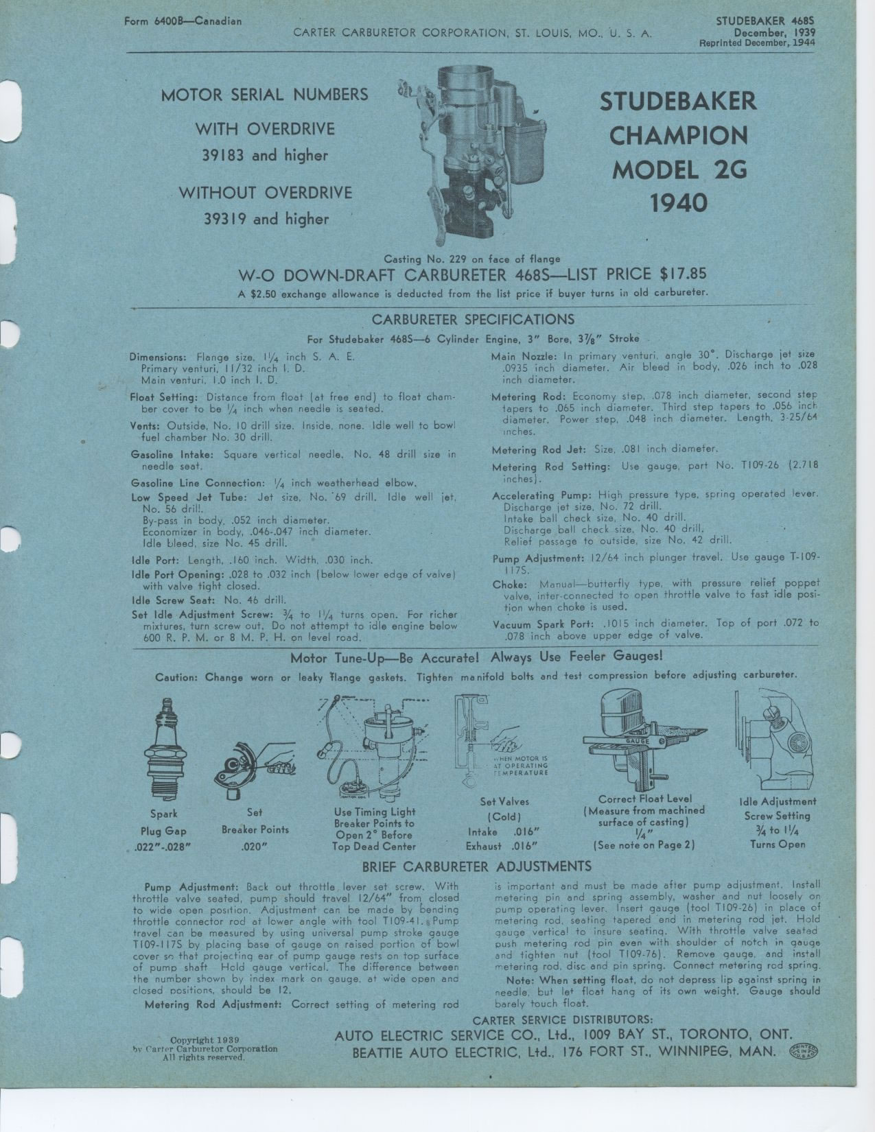
Motor Tune-Up—Be Accurate! Always Use Feeler Gauges!
Caution: Change worn or leaky Flange gaskets. Tighten manifold bolts and
test compression before adjusting carbureter.
..NEN MOTOR IS
1'U V AT OPERATING
F '-MPERATURE
Set Valves
(Cold)
Intake .016"
Exhaust .016"
Correct Float Level
(Measure from machined
surface of casting)
V4"
(See note on Page 2)
Idle Adjustment
Screw Setting
3/4 to 11/4
Turns Open
Spark Plug Gap .022"-.028"
Set
Breaker Points
.020"
es,
Use Timing Light Breaker Points to Open 2° Before Top Dead Center
Copyright 1939
by Carter Carburetor Corporation
All rights reserved.
BRIEF CARBURETER ADJUSTMENTS
is important and must be made after pump adjustment. Install metering pin
and spring assembly, washer and nut loosely on pump operating lever. Insert
gauge (tool T109-26) in place of metering rod. seating tapered end in metering
rod jet. Hold gauge vertical to insure seating. With throttle valve seated
push metering rod pin even with shoulder of notch in gauge and tighten nut
(tool T109-76). Remove gauge, and install metering rod. disc and pin spring.
Connect metering rod spring.
Note: When setting float, do not depress lip against spring in needle, but
le+ float hang of its own weight. Gauge should barely touch float.
Pump Adjustment: Back out throttle lever set screw. With throttle valve seated,
pump should travel 12/64" from closed to wide open position. Adjustment
can be made by bending throttle connector rod at lower angle with tool T
109-41. r,Pump travel can be measured by using universal pump stroke gauge
TI09-117S by placing base of gauge on raised portion of bowl cover se that
projecting ear of pump gauge rests on top surface of pump shaft Held gauge
vertical. The difference between the number shown by index mark on gauge,
at wide open and closed nositions, should be 12.
Metering Rod Adjustment: Correct setting of metering rod
|