CARBURETORS: STROMBERG
AIR LEAKS
Fig. 2. Relative amounts of air, gasoline fuel vapor and exhaust
gas in cylinder at beginning of compression. FULL POWER, FULL
OPEN THROTTLE.
Fig. 4. Relative amounts of air, gasoline fuel vapor, and exhaust
gas in cylinder. ENGINE at LIGHT LOAD and NEARLY CLOSE ) THROTTLE
with AIR LEAKS in IN-TAKE MANIFOLD.
Note normal amount of fuel but excess amount of air.
Idling cylinder charge: In order to make the engine idle or give
less than full power, it is necessary that both fuel charge and
air charge be reduced, by closing the throttle.
Illustration (Fig. 3) shows the relative amounts of air, fuel vapor,
and exhaust—all shown in the volume they would occupy at
atmospheric pressure —when the engine is idling.
Exhaust leaks. Fig. 5 shows how a leaking exhaust valve may admit
more than the natural quantity of exhaust in the cylinder and intake
system. Such a condition will make the engine miss idling on any
such cylinder and fire weak in the same cylinder up to speeds as
high as 30 m.p.h.
Fig. 5. Relative amounts of air, gasoline fuel vapor, and exhaust
gas: engine at LIGHT LOAD and NEARLY CLOSED THROTTLE, with EXHAUST
VALVE LEAK. Normal amount of fuel and air but large amount of exhaust
gas.
Large exhaust leaks can even re-duce the air charge by lowering
the suction in the cylinder.
Fig. 3. Relative amounts (shown in volumes at atmospheric pressure),
of air, gasoline uel vapor, and exhaust gas in cylinder at be-ginning
of compression. ENGINE IDLING, THROTTLE CLOSED.
Actually the cylinder contents expand to fill the whole space,
at less than half atmospheric pressure.
It will be noted that the amount of exhaust taken into the cylinder
is the same as when the engine has received a full air charge.
Since at atmospheric pressure these gases do not fill the cylinder
space, they expand to considerably less than atmospheric pressure,
or as commonly expressed, when the engine is idling, there is a
strong vacuum in the cylinder and intake manifold.
The lower air pressure and larger percentage of exhaust when the
engine is under part load result in a tendency of the mixture to
burn more slowly and it is necessary to have a slightly richer
mixture, also more spark advance is required than at full power
at the same speed.
Air leaks: On account of the high vacuum existing in the intake
system during closed throttle running, any small leak opening will
admit considerable extra air. Such leakage has a larger proportional
effect because the opening at the carburetor throttle is small.
A very small air leak opening is sufficient to interfere with smooth
running of the engine under these conditions.
Illustration (Fig. 4) shows how air can leak into the intake system
at the carburetor flange joint, also through the intake valve guide.
Leakage at either of these points will make the engine idle irregularly
and may make it impossible to throttle down to low speeds.
When such a condition exists the engine will seem to fire best
with a rich mixture setting; in other words, an engine cannot run
smoothly on a lean mixture when there is an exhaust valve leak.
The presence of exhaust valve leaks is indicated by an irregular
exhaust sound at the muffler outlet when the engine is idling.
Effect of "overlap" valve timing: This is a valve timing
often used on racing engines, and on a few passenger car engines,
with which the intake valve opens before the exhaust valve of the
same cylinder has closed.
As previously explained, there is a strong vacuum in not only
the cylinder but also the intake manifold, during partly closed
throttle running.
With the overlapped valve timing, the instant the intake valve
opens, a flow begins from the exhaust manifold, across the cylinder,
into the intake manifold, as shown in Fig. 6. This flow lasts until
the exhaust valve has closed.
After the exhaust valve has closed, all this exhaust is drawn
back into the ,4rylinder again, as the piston goes down on it's
suction stroke, with the result that the fuel charge is mixed with
considerably more than the normal amount of exhaust gas, as will
be seen by comparing the diagram of Fig. 6 with Fig. 3.
Previous page 1927
Supplement Home Next page 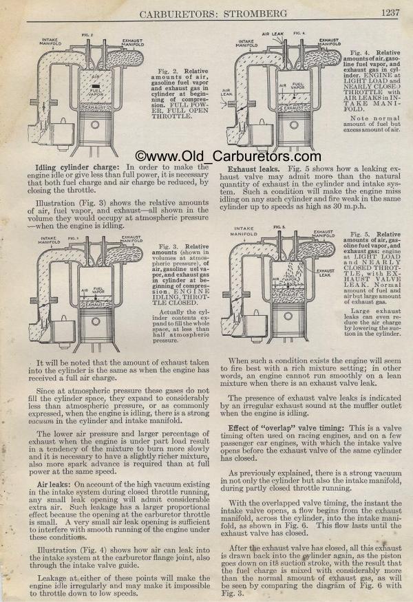
|