CARBURETORS: ZENITH
From this well, through passages Number 7, the and tube (9), draws
fuel, and through idling air valve fuel flows to the (in this
case) double cap jet. This (1) draws air, forming the proper
mixture for start-is formed by the two outer pieces under Number
4. ing and idling the engine.
Number 5 designates the main air intake of the carburetor. The
amount of air necessary to meet the demands of the engine is measured
through the choke tube (X) (see Fig. 4).
This is seen as the restricted tube held in place by the set screw
just above the compound nozzle.
Idling and Starting Jet
This idling jet (2) (Fig. 5) is an auxiliary to the compound nozzle
and operates only when the throttle is just cracked open.
The idling tube (9) projects downward to the bottom of the well
which is filled with fuel when the engine is at rest.
Cranking the engine causes a strong suction over the throttle which,
acting through the idling jet (2)
When the engine is idling the well is about half full of fuel.
This provides a reserve for acceleration as, when the throttle
is open, this f uel rushes through passages (7) Fig. 4, to balance
the air passing by the compound nozzle.
Practice
The Zenith principle, illustrated and explained in preceding pages,
is incorporated in every Zenith carburetor.
The illustrations (Figs. 6, 7, and S) show how it is adapted to
actual working conditions, through the use of parts governing the
flow of air and gasoline which can be varied to meet individual
requirement, but which become integral parts of the carburetor
not subject to iris-adjustment.
INSTALLING, ADJUSTING, AND CHECKING A ZENITH CARBURETOR
The type and size of carburetor to be used can be determined fronn
the one to be replaced, or by measuring inlet manifold opening
and refer to Fig. 9 and table below.
Carburetors come in nominal sizes having actual diameters of barrels
(B) and distance between bolt hole centers in flanges (A) as follows:
Nominal Size Actual Size (B) Bolt Center (A)
7/8" 1 1/16" 2 1/4 "
1 1 3/16" 2 3/8 "
1 1/4" 1 7/16" 2 11/16"
1 1/2" 1 11/16" 2 15/16"
13/4" 1 15/16" 3 5/16"
2 2 3/16" 3 9/16"
Model and size are designated by the marking on carburetor. The
model appears in letters and the size in figures. For example,
ST-4, or U4 means a model ST or U carburetor 1" size.
The different figure markings and corresponding sizes are as follows:
the figure marking 312 means %" size; 4, 1" size; 5,
11.i"; 6, 112'; 7, 1)4 8, 2".
There are two main types—the vertical which hangs from the
manifold; and the horizontal which bolts to the side of the cylinder
block.
Carburetor Adjustment
The following instructions will enable you to figure out what is
necessary to correct an adjustment.
To correctly and quickly work out the adjustment you need to know
what to change to accomplish a certain result and, at the same
time, what effect that change will have on other points of operation.
Note the following carefully and you will have little difficulty
in "working out" or correcting an adjustment.
From Zenith carburetor instruction book (Zenith-Detroit Corporation,
Detroit, Mich.). These instructions can also be used to check carburetors
already installed in order to see if they have the proper size
choke tube, main jet, and idling jet.
Fig. 10. Choke tube or venturi (arrow shows where size is stamped
in millimeters). Its job is to measure the air through the carburetor.
In size it should be large enough to supply all the air needed
for maximum speed, and small enough to keep the air moving fast
enough at low speed to completely atomize the fuel.
Fig. 11. Main jet (size stamped on base). This is the long jet
(5) Fig. 4, page 1294. It is directly connected with the float
chamber and will vary in amount of fuel flowed with the speed of
the engine. Its effect is most noticeable at high speed.
In the older types of carburetors such as Models L, 0, and HP,
its size is marked in 1/100ths of a millimeter.
In the later types the mark signifies the number of 1/100ths of
a millimeter divided by 5.
Examples of Markings of Jets
Model L (old model) main jet, having a hole 1 millimeter in diameter,
is 100 millimeters and consequently marked 100. Model U (later
model) main jet, having a hole 1 millimeter in
diameter, is l0U millimeters and as 100=5=20, therefore it is 100
marked 20.
The main jets are made in various sizes progressing in steps of
5/100ths of a millimeter.
Model T. (old model) main jets come in sizes as low as 60 up to
as high as 250, and in this order-100-105-110, etc.
Equivalent sizes of Model U, ST, and SV (later model) main jets
would be from 12 up to 53, and in this order-20-21-22-23.
See Tables on page 1296 for sizes to use.
Fig. 12. Compensating jet (left) (size stamped on base). This is
the short jet (6) (Fig. 4, page 1294).
It empties into the well (J) (Fig. 3, page 1293) which is open
to the atmosphere and accordingly is not affected by the suction.
It flows the same amount of fuel at all speeds but its effect is
most noticeable at low speed such as climbing a hill or pulling
through deep sand and mud and in acceleration. The compensating
jets are drilled in the same manner as the main jets.
Fig. 13. Cap jet. This is not a measuring jet and bears no mark
and is made in one size only. The fuel measured through the comp.
jet goes through channel hole (7) (Fig. 4) and out of cap jet into
carburetor barrel (t ite barrel is that part which holds the choke
tube and throttle valve).
Fig. 14. Idling jet (size stamped on nut at top). This is the jet
(2) (Fig. 4) and its sole function is to supply fuel for closed
throttle operation. Immediately the throttle is opened it is put
out of action as the fuel goes into carburetor through cap jet.
Fig. 9
Fig. 10 (left). Choke tube or venturi.
Fig. 11 (right). Main jet.
Fig. 14 Fig. 13
Previous page 1927
Supplement Home Next page 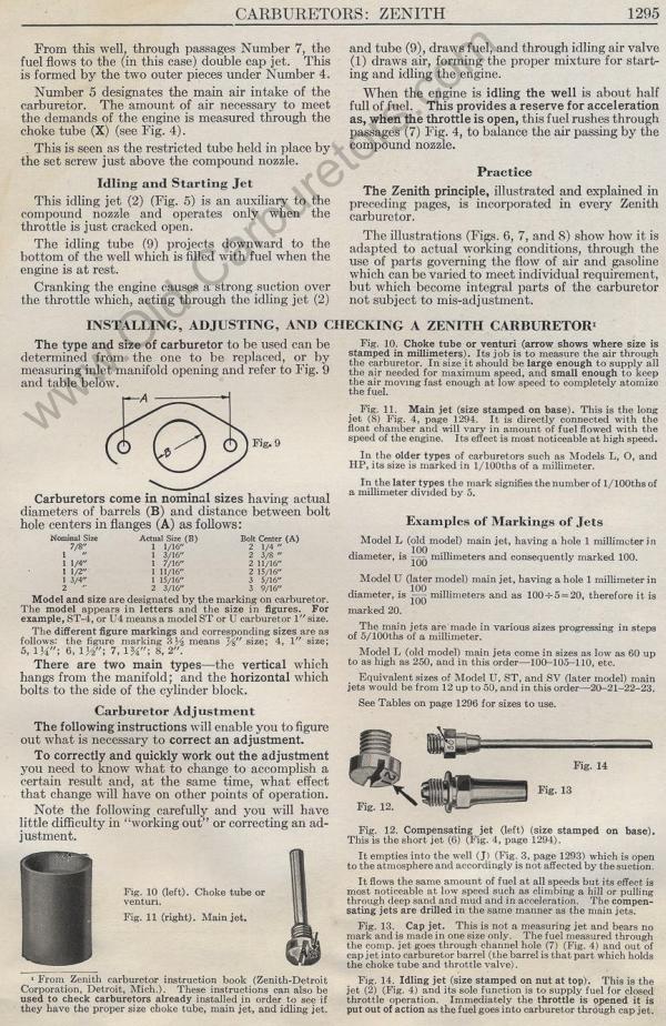
|