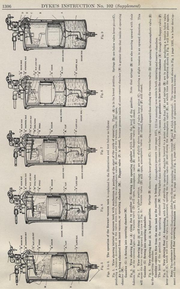
StewartThe operation
of the Stewart vacuum tank is explained in the
illustrations and text below as follows: Fig. 7. View showing float (A) still rising and in a higher position.
Springs (Si are now slightly above center of valve lever pivot
(C), producing a slight tension in an upward direction. This will
cause the lever to snap upward (see view ill Fig. 8). Vacuum valve
(D) still open, atmospheric valve (E) closed, flapper valve (F)
still closed. Fig. 8. View showing float (A) in highest position. Springs (B)
above valve lever pivot (C) ; lever having moved upward thus closing
the vacuum valve (D) and opening the atmospheric valve (E) to the
operating chamber. Fig. 9. View showing float (A) descending, with level of gasoline in operating chamber lowered to a point where the float (A) and springs (B) are in position, producing a tension below valve lever pivot (C), which will move the valve lever downward, opening the vacuum valve (D) and closing the atmospheric valve (E), at which time the operation shown in Fig. 5 will take place again. Note: The reference letters on above illustrations differ from those in preceding illustrations (except M and N which correspond). The vacuum tank shown in Fig. 1 page 1303, is a later development and has the improved float operating mechanism (see T, Fig. 1, page 1303 and Fig. 3, page 1304). The principle of operation is the same however. Previous page 1927 Supplement Home Next page
|