ENGINE BEARINGS
If any bearing has no leakage, it indicates a probable total
obstruction somewhere in the passages feeding that bearing.
It is essential therefore that every main and rod bearing show
some leakage, as the absence of drip-page means obstructions
in the oil passages.
On those few engines where the front end drive is pressure lubricated
by a separate lead always in register, there will be a solid
stream of oil leakage out the end of the pipe supplying the gears
or chain. Facilities should be provided to catch this oil, or
the leakage may be stopped during the test by closing end of
pipe with wooden plug. The plug should of course be removed after
making observations on the bearings.
Testing for Partially Clogged Oil Passages
The tank outfit can also be used to advantage for testing the drilled
passages in a crankshaft when it is removed from the engine or
when the bearings have been taken off. It can also be utilized
for testing the condition of the oil passages in crankcase or
cylinder block, as shown at Figs. 3A and 3B.
Air pressure is generally utilized for cleaning out and testing
these passages, but air being a gas (not fluid) will not detect
a partial obstruction because it will pass through even though
the passage be almost totally obstructed.
The use of oil with pressure not to exceed 5 to 10 lbs. will indicate
by the volume being discharged from the crankshaft holes whether
or not the passage being tested is partially obstructed.
If passages are absolutely clean the stream of oil coming out of
drilled hole will be equal in diameter to the hole. A stream smaller
in diameter than the crankshaft metering hole indicates a partial
stoppage.
When using the test tank for detecting obstructions in the passages
of a drilled crankshaft, proceed in the manner as shown at Fig.
3.
PP..RE/AL ESrEM Fig. 3. By using not more than 5 lbs. pressure,
tank may be used for testing drilled passages in crank-shaft. Air
test alone, without the oil, is not depend-able, as it will not
detect partial stoppage in shaft.
G>- 'POSinonE
Fig. 3A. Testing oil passages in Studebaker "Big Six" engine
for leakage, as an example. Plug openings (F), (E), and each main
bearing hole indicated at (A), (B), (C), and (D) with tight fitting
wooden plugs. Then make hook-up as shown in Fig. 3B.
Fig. 3B (continued from Fig. 3A). Place oil in test tank with (L)
closed, and pump air into it until the gauge (J) shows a pressure
of 30 lbs. Then open (L) and observe each of the main bearing bulkhead
glands at (G) (Fig. 3A). There should be no leakage whatsoever
at these points.
To test for obstructions in oil passages, release the pressure
in the oil test tank. Remove main bearing oil-hole plugs at (A),
(B), (C), and (D) (Fig. 3A). Reconnect test tank as shown
Fig. 3B
at Fig. 3B, and pump pressure until gauge registers 5 lbs. Now
open valve (L) and observe amount of oil coming out of each of
the main bearing oil-supply holes at (A), (B), (C), and (D) .
If the passages are clear, approximately a full stream will be
ejected at (A), (B), (C), and (D).
If the passages are partially clogged, this will be indicated by
a smaller stream.
If the passage is totally obstructed, no oil will be ejected for
the particular main bearing oil-supply hole.
Note the oil-test tank is connected at oil pump outlet fitting
(II) in Fig. 3A.
Another Method of Testing for Loose Bearings
Another method of testing for loose bearings on a pressure-lubricated
engine consists in
~~ - using a dial gauge
.1, (G) (Fig. 4) supplied
4160 ting with an (T) adapter which al-with an lowsit to be screwed
into the oil-supply hole in the bearing cap (D) as shown. By using
a jack or by means of a special fitting which enables the shaft
(S) to be moved up and down in its bearing, the amount of movement
or looseness may be read directly on the gauge.
Conditions Other Than Looseness Which May Cause Excessive Oil Leakage
from Bearings
The following illustrations (Figs. 5, 6, and 7) show that excessive
oil leaks may occur from
1. Poorly filed connecting-rod caps (Fig. 5).
2. Improper oil groove, or reservoir (Fig. 6).
3. Improperly fitted shims (Fig. 7).
OIL WILL LEAK OUT HERE.
Fig. 5. Left: Careless filing has left babbitt part of cap and
rod below level of cap and rod forging.
Center: If the cap assembly is reduced on a piece of emery cloth
on flat surface, cap will be flat and square. As shown, ends are
rounded and will leak oil.
Right: When properly reduced or lapped, cap and rod and both bearing
halves will appear as shown.
Previous page 1927
Supplement Home Next page 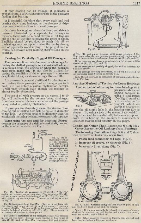
|