Skip to: site menu | section menu | main content
Loosen the three bolts "A" in Fig. 219, that attach
the steering gear to the frame on the Master model passenger cars
and the three cover stud nuts "A" in Fig. 220 on the
Master Conventional, and 1 1/2 -ton trucks and Standard passenger
models, 3 turn only.
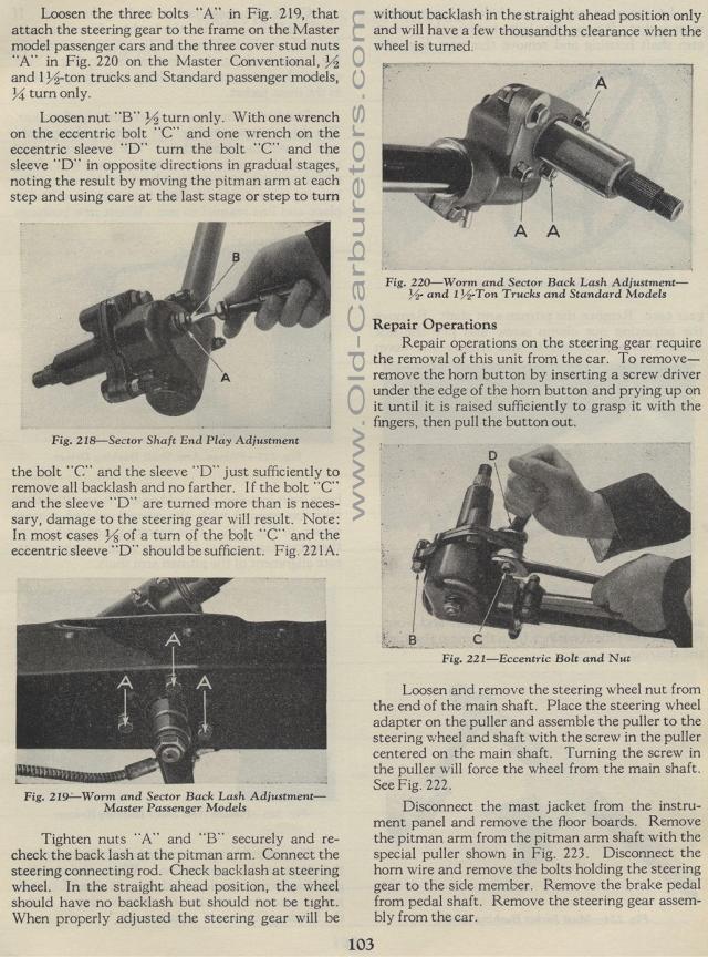
Loosen nut "B" 1/2 turn only. With one wrench on the eccentric bolt "C" and
one wrench on the eccentric sleeve "D" turn the bolt "C" and
the sleeve "D" in opposite directions in gradual stages, noting the
result by moving the pitman arm at each step and using care at the last stage
or step to turn
Sector Shaft End Play Adjustment
the bolt "C" and the sleeve "D" just sufficiently to remove all backlash and no farther. If the bolt "C" and the sleeve "D" are turned more than is necessary, damage to the steering gear will result. Note: In most cases % of a turn of the bolt "C" and the eccentric sleeve "D" should be sufficient. Fig. 221A.
Fig. 219— Worm and Sector Back Lash Adjustment—
Master Passenger Models
Tighten nuts "A" and "B" securely and re-check
the back lash at the pitman arm. Connect the steering connecting
rod. Check backlash at steering wheel. In the straight ahead position,
the wheel should have no backlash but should not be tight. When
properly adjusted the steering gear will be
without backlash in the straight ahead position only and will have
a few thousandths clearance when the wheel is turned.
Fig. 220— Worm and Sector Back Lash
Adjustment —and
1 1/2 -Ton Trucks and Standard Models
Repair Operations
Repair operations on the steering gear require the removal of this
unit from the car. To remove—remove the horn button by inserting
a screw driver under the edge of the horn button and prying up
on it until it is raised sufficiently to grasp it with the fingers,
then pull the button out.
Loosen and remove the steering wheel nut from the end of the main
shaft. Place the steering wheel adapter on the puller and assemble
the puller to the steering wheel and shaft with the screw in the
puller centered on the main shaft. Turning the screw in the puller
will force the wheel from the main shaft. See Fig. 222.
Disconnect the mast jacket from the instrument panel and remove
the floor boards. Remove the pitman arm from the pitman arm shaft
with the special puller shown in Fig. 223. Disconnect the horn
wire and remove the bolts holding the steering gear to the side
member. Remove the brake pedal from pedal shaft. Remove the steering
gear assembly from the car.
Fig. 221—Eccentric Bolt and Nut