Old Buick Carburetors : BUICK EIGHT MODELS 60 70 80 90 1940Previous | Home | Next |
 |
distance between upper edge of choke valve and inner wall of air horn should be 3/16". (Use gauge T109-28). Adjustment can be made by bending lip on fast idle connector link.
With throttle wide open, pusn choker valve open. Choke should lock in wide
open position. If it does not lock, re-check unloader adjustment. Closing the
throttle will release choker valve. Choker trip lever is notched out for this
setting. Choker mechanism must be absolutely free in any position.
FAST IDLE ADJUSTMENT: With throttle stop screw backed out until throttle valves
are completely closed, hold choke valve tightly closed and place .030" gauge
(T109-29) between throttle valve and bore of carbureter, side opposite post.
Adjust fast idle arm screw to rest on top, or upper step of fast idle cam
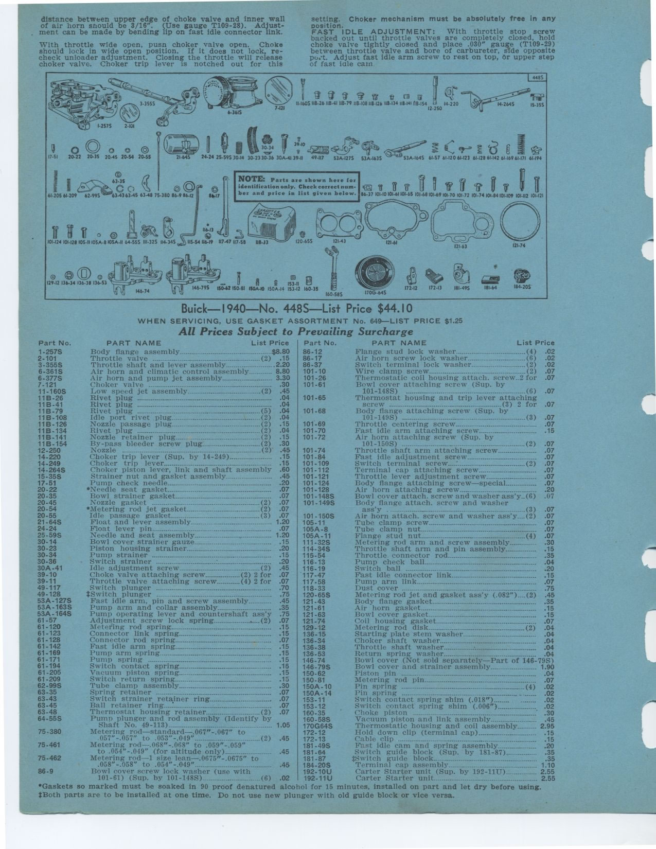
Buick— 1940—No. 448S—List Price $44.10
WHEN SERVICING, USE GASKET ASSORTMENT No. 649—LIST PRICE $1.25 All Prices
Subject to Prevailing Surcharge
NOTE: Parts are shown here for identification only. Check correct number and
price in list given below.
Body flange assembly $8.80
Throttle valve (2) .15
Throttle shaft and lever assembly 2.20
Air horn and climatic control assembly 8.80
Air horn and pump jet assembly 3.30
Choker valve 30
Low speed jet assembly (2) .45
Rivet plug 04
Rivet plug ...--°- 04
Rivet plug ------------°---- (5) 04
Idle port rivet plug (2) 04
Nozzle passage plug_ (2) 15
Rivet plug (2) 04
Nozzle retainer plug (2) 15
By-pass bleeder screw plug (2) 30
Nozzle ---- -_._. .._--_. . . (2) 45
Choker trip lever (Sup. by 14-249) 15
Choker trip lever 15
Choker piston lever, link and shaft assembly 60
Strainer nut and gasket assembly ... 45
Pump check needle 20
*Needle seat gasket 07
Bowl strainer gasket 07
Nozzle gasket (2) 07
*Metering rod jet gasket (2) 07
Idle passage gasket (3) 07
Float and lever assembly 1 20
Float lever pin---- 07
Needle and seat assembly 1 20
Bowl cover strainer gauze 15
Piston housing strainer 20
Pump strainer 15
Switch strainer : 20
Idle adjustment screw (2) .45
Choke valve attaching screw (2) 2 for .07
Throttle valve attaching screw (4) 2 for .07
Switch plunger 70
tSwitch plunger ... 75
Fast idle arm, pin and screw assembly 45
Pump arm and collar assembly 35
Pump operating lever and countershaft ass'y .75
Adjustment screw lock spring (2) .07
Metering rod spring 15
Connector link spring 15
Connector rod spring 07
Fast idle arm spring 15
Pump arm spring 15
Pump spring 15
Switch contact spring 15
Vacuum piston spring ... 15
Switch return spring 15
Tube clamp assembly 30
Spring retainer 07
Switch strainer retainer ring 07
Ball retainer ring 07
Thermostat housing retainer (2) .07
Pumn plunger and rod assembly (Identify by
Shaft No. 49-113)- - 1.05
Metering rod—standard—.067"-.067" to
057"-.057" to .053"-.049" (2) .45
Metering rod—.068"-.068" to .059"-.059"
to .054"-.049" (for altitude only) 45
Metering rod—1 size lean—.0675"-.0675" to
.058"-.058" to .054"-.049" 45
Bowl cover screw lock washer (use with
101-61) (Sup. by 101-148S) (6) .02PART NAME List Price
Flange stud lock washer (4) .02
Air horn screw lock washer (6) .02
Switch terminal lock washer (2) .02
Wire clamp screw (2) .07
Thermostatic coil housing attach. screw..2 for .07 Bowl cover attaching screw
(Sup. by
101-148S) (6) .07
Thermostat housing and trip lever attaching
screw (3) 2 for .07
Body flange attaching screw (Sup. by
101-149S) (3) .07
Throttle centering screw 07
Fast idle arm attaching screw 15
Air horn attaching screw (Sup. by
101-150S) __ (2) 07
Throttle shaft arm attaching screw 07
Fast idle adjustment screw 07
Switch terminal screw (2) 07
Terminal cap attaching screw 07
Throttle lever adjustment screw 07
Body flange attaching screw—special 07
Air horn attaching screw 20
Bowl cover attach. screw and washer ass'y (6) 07
Body flange attach. screw and washer
ass'y (3) 07
Air horn attach. screw and washer ass'y (2) 07
Tube clamp screw 07
Tube clamp nut 07
Flange stud nut °°--- (4) 07
Metering rod arm and screw assembly _ .30
Throttle shaft arm and pin assembly 15
Throttle connector rod 35
Pump check ball 04
Switch ball 20
Fast idle connector link 15
Pump arm link 07
Dust cover 75
Metering rod jet and gasket ass'y (.082")....(2) 45
Body flange gasket 35
Air horn gasket 15
Bowl cover gasket 15
Coil housing gasket 07
Metering rod disk (2) 04
Starting plate stem washer 04
Choker shaft washer 04
Throttle shaft washer : 04
Return spring washer 04
Bowl cover (Not sold separately—Part of 146-79S)
Bowl cover and strainer assembly 1 90
Piston pin ° °-- 04
Metering rod pin 07
Pin spring (4) 02
Pin spring 02
Switch contact spring shim (.018") 02
Switch contact spring shim (.006") 02
Choke piston 30
Vacuum piston and link assembly 45
Thermostatic housing and coil assembly 2 95
Hold down clip (terminal cap) 15
Cable clip 15
Fast idle cam and spring assembly 20
Switch guide block (Sup. by 181-87) 35
plwitch guide block 35
Terminal cap assembly-_..- .. 1.10
Carter Starter unit (Sup. by 192-11U)_ 2.55
*Gaskets so marked must be soaked in 90 proof denatured alcohol for 15 minutes,
installed on part and let dry before using. :Both parts are to be installed
at one time. Do not use new plunger with old guide block or vice versa.