Old Buick Carburetor : BUICK EIGHT 1939 Early 1940 McLaughlin Buick 8 Model 44 1939 Early 1940Previous | Home | Next |
 |
Form 6377C—Canadian
Replacing Forms 6349-A-6377A-6377B
.BUICK 419S-440S
July, 1939
Reprinted June, 1944
MOTOR SERIAL NUMBERS
(U. S. A. PRODUCTION)
1939 (4I9S) 43572652 and higher Early 1940 (440S) 43671415 to 43672299
43672642 and higher
SERIAL NUMBERS
(CANADIAN PRODUCTION)
Oshawa 944—01930 and higher Except 944—02022, 02024, 02026 Regina
944—30176 and higher Except 944—80223, 80224, 80226,
80227, 80228
BUICK EIGHT
1939 Early 1940
McLaughlin Buick 8
Model 44
1939 Early 1940
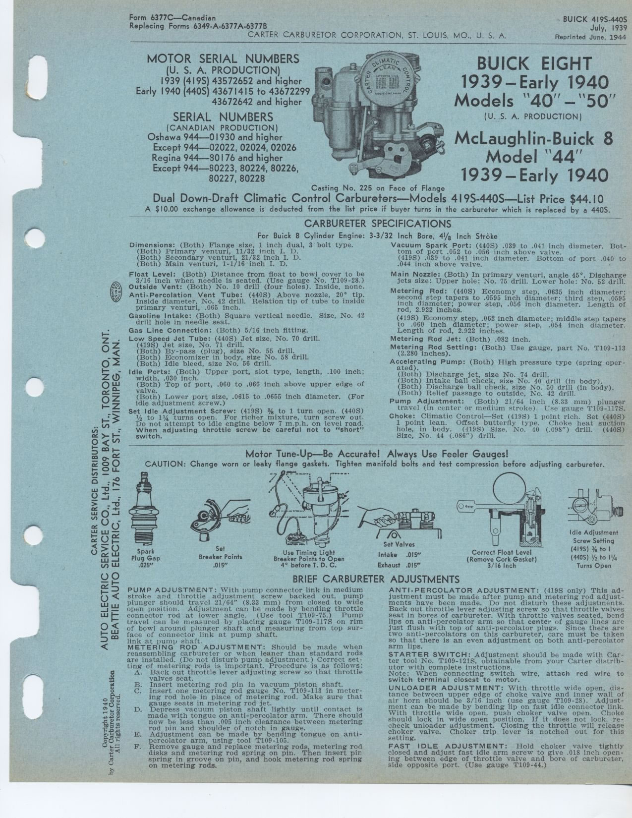
Casting No. 225 on Face of Flange
Dual Down-Draft Climatic Control Carbureters—Models 419S-440S—List
Price $44.10
A $ 10.00 exchange allowance is deducted from the list price if buyer turns
in the carbureter which is replaced by a 440S.
Vacuum Spark Port: (440S) .039 to .041 inch diameter. Bottom of port .052 to
.056 inch above valve.
(419S) .039 to .041 inch diameter. Bottom of port .040 to .044 inch above valve.
Main Nozzle: (Both) In primary venturi, angle 45°. Discharge jets size:
Upper hole: No. 75 drill. Lower hole: No. 52 drill.
Metering Rod: (440S) Economy step, .0635 inch diameter: second step tapers
to .0595 inch diameter; third step, .0595 inch diameter; power step, .056 inch
diameter. Length of rod, 2.922 inches.
(419S) Economy step, .062 inch diameter; middle step tapers to .060 inch diameter;
power step, .054 inch diameter. Length of rod, 2.922 inches.
Metering Rod Jet: (Both) .082 inch.
Metering Rod Setting: (Both) Use gauge, part No. T109-113 (2.280 inches).
Accelerating Pump: (Both) High pressure type (spring operated).
(Both) Discharge jet, size No. 74 drill.
(Both) Intake ball check, size No. 40 drill (in body). (Both) Discharge ball
check, size No. 50 drill (in body). (Both) Relief passage to outside, No. 42
drill.
Pump Adjustment: (Both) 21/64 inch (8.33 mm) plunger travel On center or medium
stroke). Use gauge T109-117S. Choke: Climatic Control—Set (419S) 1 point
rich. Set (440S) 1 point lean. Offset butterfly type. Choke heat suction hole,
in body. (419S) Size, No. 40 (.098") drill. (440S) Size, No. 44 (.086")
drill.
Motor Tune-Up—Be Accurate! Always Use Feeler Gauges!
CAUTION: Change worn or leaky flange gaskets. Tighten manifold bolts and test
compression before adjusting carbureter.
Idle Adjustment Screw Setting (419S) % to I (440S) /2 to 1¼ Turns Open
CARBURETER SPECIFICATIONS
For Buick 8 Cylinder Engine: 3-3/32 Inch Bore, 41/8 Inch Stroke
Dimensions: (Both) Flange size, 1 inch dual, 3 bolt type. (Both) Primary venturi,
11/32 inch I. D.
(Both) Secondary venturi, 21/32 inch I. D.
(Both) Main venturi, 1-1/16 inch I. D.
Float Level: (Both) Distance from float to bowl cover to be 3/16 inch when
needle is seated. (Use gauge No. T109-28.)
Outside Vent: (Both) No. 10 drill (four holes). Inside, none. Anti-Percolation
Vent Tube: (440S) Above nozzle, 20° tip. Inside diameter, No. 42 drill.
Relation tip of tube to inside primary venturi, .065 inch.
Gasoline Intake: (Both) Square vertical needle. Size, No. 42 drill hole in
needle seat.
Gas Line Connection: (Both) 5/16 inch fitting.
Low Speed Jet Tube: (440S) Jet size, No. 70 drill.
(419S) Jet size, No. 71 drill.
(Both) By-pass (plug), size No. 55 drill.
(Both) Economizer in body, size No. 58 drill.
(Both) Idle bleed, size No. 56 drill.
Idle Ports: (Both) Upper port, slot type, length, .100 inch; Z
width, .030 inch.
0 W (Both) Top of port, .060 to .066 inch above upper edge of
— valve.
(Both) Lower port size, .0615 to .0655 inch diameter. (For idle adjustment screw.)
Set Idle Adjustment Screw: (419S) % to 1 turn open. (440S)
1/2 to 11/, turns open. For richer mixture, turn screw out. Do not attempt to
idle engine below 7 m.p.h. on level road. When adjusting throttle screw be careful
not to "short" switch.
Spark Plug Gap .025"
Set
Breaker Points
.015"
Use Timing Light Breaker Points to Open 4° before T. D. C.
/v\
Set Valves Intake .015"
Exhaust .015"
Correct Float Level
(Remove Cork Gasket)
3/16 Inch
BRIEF CARBURETER ADJUSTMENTS
0 I
0< W w
w I—0
D m
PUMP ADJUSTMENT: With pump connector link in medium stroke and throttle adjustment
screw backed out, pump plunger should travel 21/64" (8.33 mm) from closed
to wide open position. Adjustment can be made by bending throttle connector rod
at lower angle. (Use tool T109-75.) Pump travel can be measured by placing gauge
T109-117S on rim of bowl around plunger shaft and measuring from top surface
of connector link at pump shaft.
link at pump shaft.
< METERING ROD ADJUSTMENT: Should be made when reassembling carbureter or
when leaner than standard rods are installed. (Do not disturb pump adjustment.)
Correct set-
ting of metering rods is important. Procedure is as follows:
A. Back out throttle lever adjusting screw so that throttle valves seat.
B. Insert metering rod pin in vacuum piston shaft.
C. Insert one metering rod gauge No. T109-113 in meter-
ing rod hole in place of metering rod. Make sure that
gauge seats in metering rod jet.
D. Depress vacuum piston shaft lightly until contact is made with tongue on anti-percolator
arm. There should now be less than .005 inch clearance between metering rod pin
and shoulder of notch in gauge.
E. Adjustment can be made by bending tongue on anti-percolator arm, using tool
T109-105.
F. Remove gauge and replace metering rods, metering rod disks and metering rod
spring on pin. Then insert pin spring in groove on pin, and hook metering rod
spring on metering rods.
ANTI-PERCOLATOR ADJUSTMENT: (419S only) This adjustment must be made after pump
and metering rod adjustments have been made. Do not disturb these adjustments.
Back out throttle lever adjusting screw so that throttle valves seat in bores
of carbureter. With throttle valves seated, bend lips on anti-percolator arm
so that center of gauge lines are just flush with top of anti-percolator plugs.
Since there are two anti-percolators on this carbureter, care must be taken so
that there is an even adjustment on both anti-percolator arm lips.
STARTER SWITCH: Adjustment should be made with Car-ter tool No. T109-121S, obtainable
from your Carter distributor with complete instructions.
Note: When connecting switch wire, attach red wire to switch terminal closest
to motor.
UNLOADER ADJUSTMENT: With throttle wide open, distance between upper edge of
choke, valve and inner wall of air horn should be 3/16 inch (use gauge T109-28).
Adjustment can be made by bending lip on fast idle connector link. With throttle
wide open, push choker valve open. Choke should lock in wide open position. If
it does not lock, re-check unloader adjustment. Closing the throttle will release
choker valve. Choker trip lever is notched out for this setting.
FAST IDLE ADJUSTMENT: Hold choker valve tightly closed and adjust fast idle arm
screw to give .018 inch opening between edge of throttle valve and bore of carbureter,
side opposite port. (Use gauge T109-44.)