Carburetors for old Dodge Trucks : CARTER VELOCITY GOVERNORPrevious | Home | Next |
 |
To reassemble primary adjusting screw and adjusting nut assembly, proceed as
follows:
Install primary adjusting nut, driving nut against seat in housing with tool
No. T109-185 (always use new part to make certain of tight fit). Start primary
adjusting screw in adjusting nut from inside of housing, then turn screw counter
clock wise with narrow screw driver until all but a few threads have engaged
the nut. Screw will be a tight fit as it will be cutting new threads in adjusting
nut fiber insert.
Insert tail of primary spring in slot in governor housing, bring against entering
edge of adjusting screw and turn screw clockwise until a few coils have been
engaged. Hook spring to governing lever link.
10. If no fiber washer was found or after the fiber washer has been removed,
proceed to set the amount of active coils ("B" specification) with
the adjusting screw.
Where a fractional number of coils is required, first adjust to the nearest
whole number of coils as described above. Then add or subtract the fractional
coil by turning the primary adjusting screw the some fraction of a turn. As
an example—if 14-3/4 coils are called for in "B" specification,
adjust to obtain exactly 15 active coils. Then turn primary adjusting screw
1/4 turn or 90° clockwise, thereby reducing the number of active coils
to 14-3/4.
Should the end coil of the primary spring contact the governor housing, or
if the primary adjusting screw is turned in so far that the slotted end becomes
flush with the adjusting nut assembly before the correct amount of coils is
obtained, it will be necesary to adjust the nut. Hold the primary adjusting
screw with screw driver so that it cannot turn, while turning the adjusting
nut with tool No. T109-185.
11. Once the correct number of active coils has been established with the
adjusting screw, set "C" dimension.
To do this, hold the primary adjusting screw with screw driver so that it cannot
turn, while turning the adjusting nut with tool T109-185. Turn clockwise to
decrease "C" dimension, counter-clockwise to increase the dimension.
When dimension is correct, tap end of wrench with a light hammer to seat adjusting
nut, as adjusting nut must be firmly seated, then recheck dimension. Insert
fiber adjusting nut seal as previously explained.
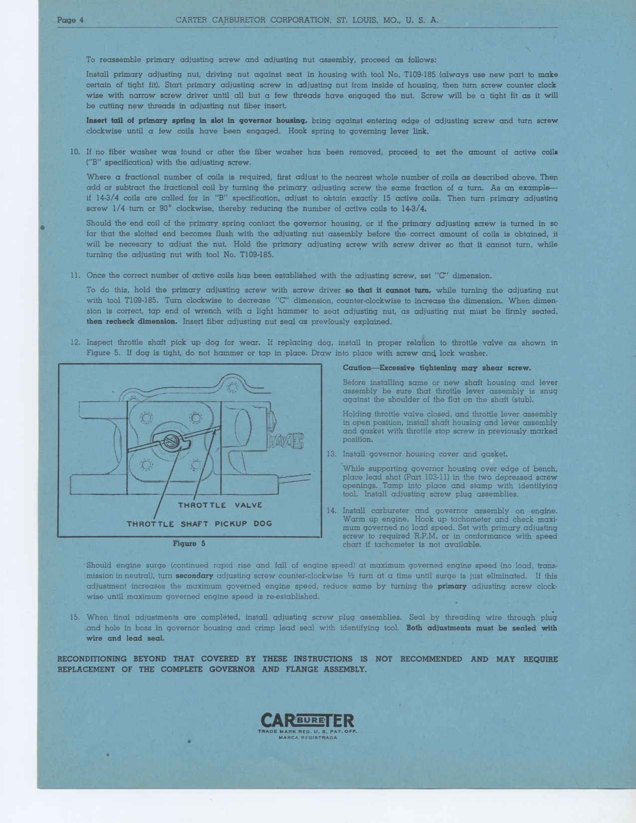
12. Inspect throttle shaft pick up dog for wear. If replacing dog, install
in proper relation to throttle valve as shown in Figure 5. If dog is tight,
do not hammer or tap in place. Draw into place with screw anct lock washer.
Caution—Excessive tightening may shear screw.
Before installing same or new shaft housing and lever assembly be sure that
throttle lever assembly is snug against the shoulder of the flat on the shaft
(stub).
Holding throttle valve closed, and throttle lever assembly in open position,
install shaft housing and lever assembly and gasket with throttle stop screw
in previously marked position.
13. Install governor housing cover and gasket.
While supporting governor housing over edge of bench, place lead shot (Part
103-11) in the two depressed screw openings. Tamp into place and stamp with
identifying tool. Install adjusting screw plug assemblies.
14. Install carbureter and governor assembly on engine. Warm up engine. Hook
up tachometer and check maxi-mum governed no load speed. Set with primary adjusting
screw to required R.P.M. or in conformance with speed
Figure 5 chart if tachometer is not available.
Should engine surge (continued rapid rise and fall of engine speed) at maximum governed engine speed (no load, trans-mission in neutral), turn secondary adjusting screw counter-clockwise 1/2 turn at a time until surge is just eliminated. If this adjustment increases the maximum governed engine speed, reduce same by turning the primary adjusting screw clock-wise until maximum governed engine speed is re-established.
15. When final adjustments are completed, install adjusting screw plug assemblies. Seal by threading wire through plug and hole in boss in governor housing and crimp lead seal with identifying tool. Both adiustments must be sealed with wire and lead seal.
RECONDITIONING BEYOND THAT COVERED BY THESE INSTRUCTIONS IS NOT RECOMMENDED
AND MAY REQUIRE REPLACEMENT OF THE COMPLETE GOVERNOR AND FLANGE ASSEMBLY.
BORE ER