Carburetors for old Dodge Trucks : DODGE TRUCK MODEL T-236 3/4 TON, 4x4 1945Previous | Home | Next |
 |
Page 4
GOVERNOR ADJUSTMENT AND SERVICE
The most reliable methods of determining whether the governor is functioning
properly are: an actual check of the maximum engine speed at full throttle
with a tachometer, or by a road test in low gear, level road, with no load
(empty truck). If the governor is functioning properly and is correctly adjusted,
it should limit the maximum engine speed to 3000-3200 R.P.M., or a road speed
of 61/2-71/2 M.P.H. in low gear with no load, without fluctuation. If governor
is inoperative or cannot be adjusted (as described in "Adjustment of Governor
on Engine") carbureter and governor assembly should be removed from manifold
and repaired as follows:
Disassembly
(I) Remove seal wire and cover plate attaching screws. Remove cover plate assembly
and gasket. Check parts for breakage or abnormal friction.
(2) 'Bend the lock washer ears away from cam retaining nut and remove nut and
cam. If cam is tight on shaft, pry gently and evenly. Remove adjustment passage
plug and turn adjusting screw clockwise until it is free of the adjusting nut.
Hold spring and turn screw counter-clockwise to remove screw from spring. Do
not remove the countersunk screws securing housing to body flange unless governor
housing is damaged.
Cleaning, Inspection and Repair
(I) Wash all parts in dry cleaning solvent or any approved carbureter cleaning
solution and dry with compressed air. If plunger rod does not slide freely
in the cylinder, or if the threads in the cover attaching screw holes have
been stripped, replace the governor housing assembly. Do not oil plunger shaft.
If threaded portion or slots of adjusting nut in governor housing have been
damaged, install new adjusting nut. Adjusting nut must be removed from governor
housing by using a drift punch from within the housing and driving the nut
toward the outer opening. A rawhide or fiber drift is preferable to prevent
damage to inner surface of adjusting nut channel. Adjusting nuts are of two
sizes and are not interchangeable. The smaller adjusting nut is brass while
+lie larger nut is die cast and grey in color. The die cast adjusting net is
used in the housing on which letters "DC" are embossed. However,
late production adjusting nuts are both of diecast material but of different
diameters. Be sure to use the one of correct diameter when rebuilding governor
assembly. Both adjusting nuts are in the repair parts package to provide the
correct part for either the large or small bore housing. When making a replacement,
be certain the new nut is a duplicate of the one removed.
(2) Install the new adjusting nut by sliding it into place, with the threaded
end down and the wide slot upward. Insert the adjusting wrench (T109-185) and
tap lightly on tool until nut bottoms in the housing.
(3) Inspect governor spring and replace if it is distorted or dam-aged. If
chain links show wear, or cam shows wear or damage, these parts should be replaced.
Be sure that adjusting screw is straight and threads have not been damaged.
The repair parts package consists of the following: Governor adjusting screw
cap, both early and late production adjusting nuts, spring, adjusting screw,
cam, chain, throttle shaft nut, and all necessary attaching screws, lock washers
and gaskets, and sealing wire.
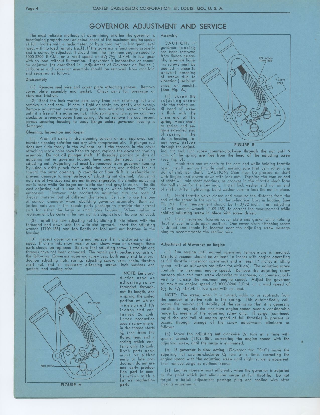
NOTE: Early production used an adjusting sere w threaded through-out its length,
and a spring, the coiled portion of w h i c h measured 11/8 inches and contained
26 coils. Later production uses a screw where-in the thread starts 7/8 inch
from the fluted head and a spring which contains only 16 coils. Both parts
used must be either early or late production, do not use one early production
part in combination with a l a t e r production part.
Assembly
CAUTION: If governor housing has been removed from flange assembly, governor
housing screws must be peened in place to prevent loosening of screws due to
vibration (use blunt chisel or punch). (See Fig. A.)
(I) Screw the adjusting screw into the spring until head of screw is flush
with the chain end of the spring. Hook chain to spring and en-gage extended
end of spring in the slot in housing. In-
sert screw driver FIGURE B
through the adjust-
ing nut and turn screw counter-clockwise through the nut until 9 coils of the
spring are free from the head of the adjusting screw (see Fig. B).
(2) Hook free end of chain to the cam and while holding throttle open, install
cam on throttle shaft, making sure that cam roller is in slot of stabilizer
shaft. CAUTION: Cam must be pressed on shaft with fingers and drawn down with
lock nut. Tapping the cam or end of shaft will ruin shaft bearings, as grooves
in the throttle shaft form the ball races for the bearings. Install lock washer
and nut on end of shaft. After tightening, bend washer ears to lock the nut
in place.
(3) Hold throttle valve closed and measure the distance from the end of the
screw in the spring to the cylindrical boss in housing (see Fig. A). This measurement
should be 1-13/32 inch. Turn adjusting nut with special wrench (TI 09-185)
to correct the measurement while holding adjusting screw in place with screw
driver.
(4) Install governor housing cover plate and gasket while holding throttle
lever in wide open position. One cover plate attaching screw is drilled and
should be located near the adjusting screw passage plug to accommodate the
sealing wire.
Adjustment of Governor on Engine
• ( I) Run engine until normal operating temperature is reached. Manifold
vacuum should be at least 16 inches with engine operating at full throttle (governor
operating) and at least 17 inches at idling speed (with an allowable reduction
for altitude). The adjusting screw controls the maximum engine speed. Remove
the adjusting screw passage plug and turn screw clockwise to decrease, or counter-clockwise
to increase the maximum engine speed. Adjust the governor to maximum engine speed
of 3000-3200 R.P.M. or a road speed of 61/2 to 71/2 M.P.H. in low gear with no
load.
NOTE: The screw, when it is turned, adds to or subtracts from the number of
active coils in the spring. This automatically calibrates the tension and stability
of the spring so that it is generally possible to regulate the maximum engine
speed over a considerable range by means of the adjusting screw only. If surge
(continued rapid rise and fall of engine speed at full throttle) is present
or occurs through change of the screw adjustment, eliminate as follows:
(a) Move the adjusting nut clockwise 1/4 turn at a time with special wrench
(T109-185), correcting the engine speed with the adjusting screw, until the
surge is eliminated.
(b) If governor is slow acting (Governor too "flat") move the adjusting
nut counter-clockwise 1/4 turn at a time, correcting the engine speed with
the adjusting screw until slight surge is apparent. Then remove surge as outlined
above.
(2) Engines operate most efficiently when the governor is adjusted to the point
which just eliminates surge at full throttle. Do not forget to install adjustment
passage plug and sealing wire after making adjustment.
FIGURE A