|
Form 6498—Canadian
DODGE 6EI
April, 1942
Reprinted April, 1944
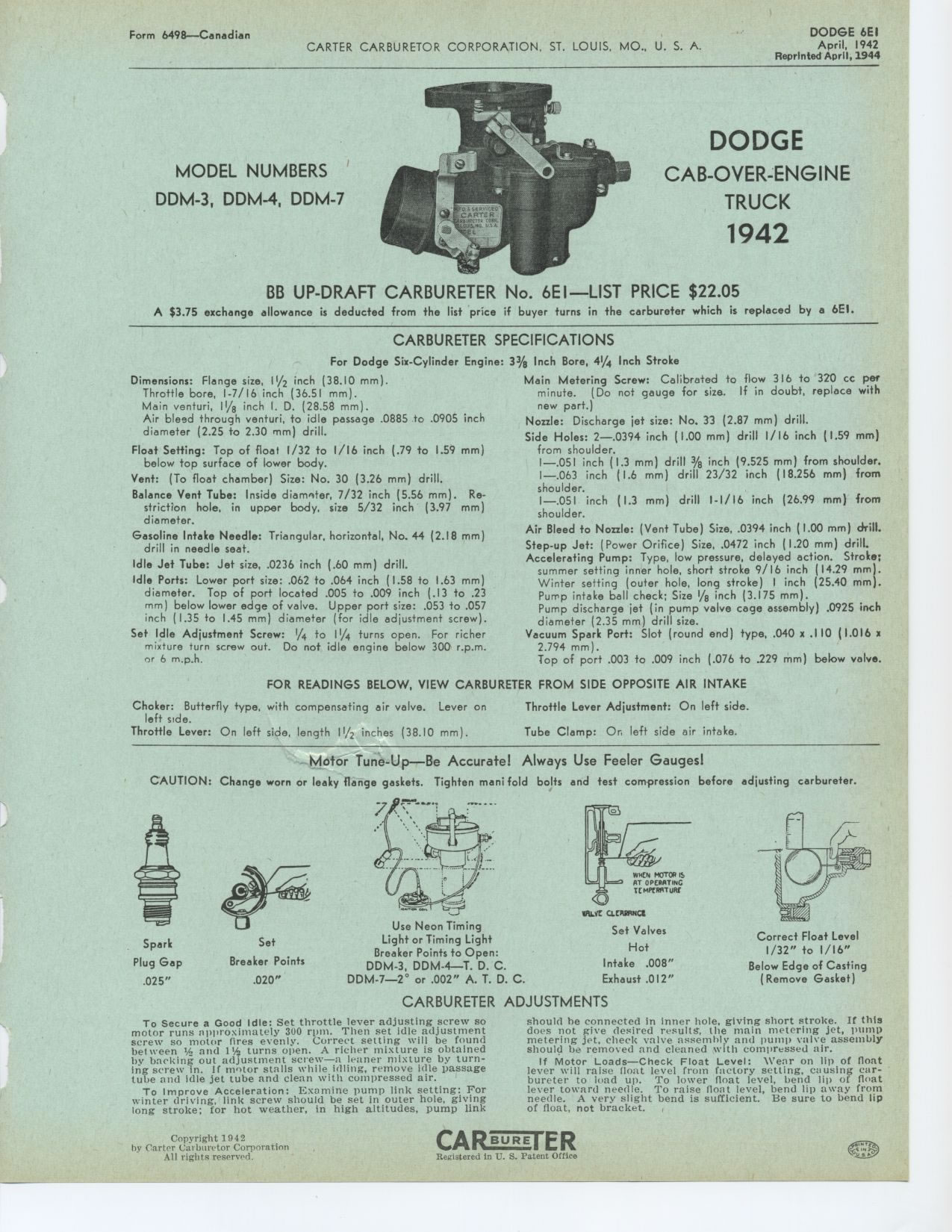
MODEL NUMBERS
DDM-3, DDM-4, DDM-7
DODGE
CAB OVER ENGINE
TRUCK
1942
BB UP-DRAFT CARBURETER No. 6EI—LIST PRICE $22.05
A $3.75 exchange allowance is deducted from the list price if buyer turns
in the carbureter which is replaced by a 6EI.
CARBURETER SPECIFICATIONS
For Dodge Six-Cylinder Engine: 3% Inch Bore, 41/4 Inch Stroke
Dimensions: Flange size, 11/2 inch (38.10 mm).
Throttle bore, 1-7/16 inch (36.51 mm).
Main venturi, 11/8 inch I. D. (28.58 mm).
Air bleed through venturi, to idle passage .0885 to .0905 inch diameter
(2.25 to 2.30 mm) drill.
Float Setting: Top of float 1/32 to 1/16 inch (.79 to 1.59 mm) below
top surface of lower body. Vent: (To float chamber) Size: No. 30 (3.26
mm) drill.
Balance Vent Tube: Inside diameter, 7/32 inch (5.56 mm). Restriction
hole, in upper body, size 5/32 inch (3.97 mm) diameter.
Gasoline Intake Needle: Triangular, horizontal, No. 44 (2.18 mm) drill
in needle seat.
Idle Jet Tube: Jet size, .0236 inch (.60 mm) drill.
Idle Ports: Lower port size: .062 to .064 inch (1.58 to 1.63 mm) diameter.
Top of port located .005 to .009 inch (.13 to .23 mm) below lower edge
of valve. Upper port size: .053 to .057 inch (1.35 to 1.45 mm) diameter
(for idle adjustment screw).
Set Idle Adjustment Screw: 1/4 to 1¼ turns open. For richer mixture
turn screw out. Do not idle engine below 300 r.p.m. or 6 m.p.h.
Main Metering Screw: Calibrated to flow 316 to 320 cc per minute. (Do
not gauge for size. If in doubt, replace with new part.)
Nozzle: Discharge jet size: No. 33 (2.87 mm) drill.
Side Holes: 2—.0394 inch (1.00 mm) drill 1/16 inch (1.59 mm) from shoulder.
—.051 inch (1.3 mm) drill 3/8 inch (9.525 mm) from shoulder. —.063
inch (1.6 mm) drill 23/32 inch (18.256 mm) from shoulder.
—.051 inch (1.3 mm) drill 1-1/16 inch (26.99 mm) from shoulder.
Air Bleed to Nozzle: (Vent Tube) Size, .0394 inch (1.00 mm) drill. Step-up
Jet: (Power Orifice) Size, .0472 inch (1.20 mm) drill. Accelerating Pump:
Type, low pressure, delayed action. Stroke;
summer setting inner hole, short stroke 9/ 16 inch (14.29 mm). Winter
setting (outer hole, long stroke) I inch (25.40 mm). Pump intake ball
check; Size 1/8 inch (3.175 mm).
Pump discharge jet (in pump valve cage assembly) .0925 inch diameter
(2.35 mm) drill size.
Vacuum Spark Port: Slot (round end) type, .040 x .110 (1.016 x 2.794
mm).
Top of port .003 to .009 inch (.076 to .229 mm) below valve.
FOR READINGS BELOW, VIEW CARBURETER FROM SIDE OPPOSITE AIR INTAKE
Choker: Butterfly type, with compensating air valve. Lever on left side.
Throttle Lever: On left side, length 11/2 inches (38.10 mm).
Throttle Lever Adjustment: On left side. Tube Clamp: On left side air
intake.
Motor Tune-Up—Be Accurate! Always Use Feeler Gauges!
CAUTION: Change worn or leaky flange gaskets. Tighten mani fold bolts
and test compression before adjusting carbureter.
Spark Plug Gap .025"
Set
Breaker Points
.020"
rnLrc C1rxawc2
Set Valves
Hot
Intake .008" Exhaust .012"
Correct Float Level
1/32" to 1/16"
Below Edge of Casting
(Remove Gasket)
Use Neon Timing
Light or Timing Light
Breaker Points to Open:
DDM-3, DDM-4-T. D. C.
DDM-7—2° or .002" A. T. D. C.
CARBURETER ADJUSTMENTS
To Secure a Good Idle: Set throttle lever adjusting screw so motor runs
approximately 300 rpm. Then set idle adjustment screw so motor fires
evenly. Correct setting will be found between t/ and 11/, turns open.
A richer mixture is obtained by backing out adjustment screw—a leaner mixture by turning screw in.
If motor stalls while idling, remove idle passage tube and idle jet tube
and clean with compressed air.
To Improve Acceleration: Examine pump link setting: For winter driving,
link screw should be set in outer hole, giving long stroke; for hot weather,
in high altitudes, pump linkshould he connected in inner hole, giving
short stroke. If this does not give desired resultg, the main metering
jet, pump metering jet, check valve assembly and pump valve assembly
should be removed and cleaned with compressed air.
If Motor Loads—Check Float Level: Wear on lip of float lever will raise
^oat level from factory setting, causing carbureter to load up. To lower
float level, bend lip of float lever toward needle. To raise float level,
bend lip away from needle. A very slight bend is sufficient. Be sure to bend
lip of float, not bracket. ,
Copyright 1942
|