|
CARTER CARBURETOR CORPORATION, ST. LOUIS, MO., U. S. A.
Form 6082A—Canadian
HUPMOBILE 258S
February, 1933
Reprinted July, 1939
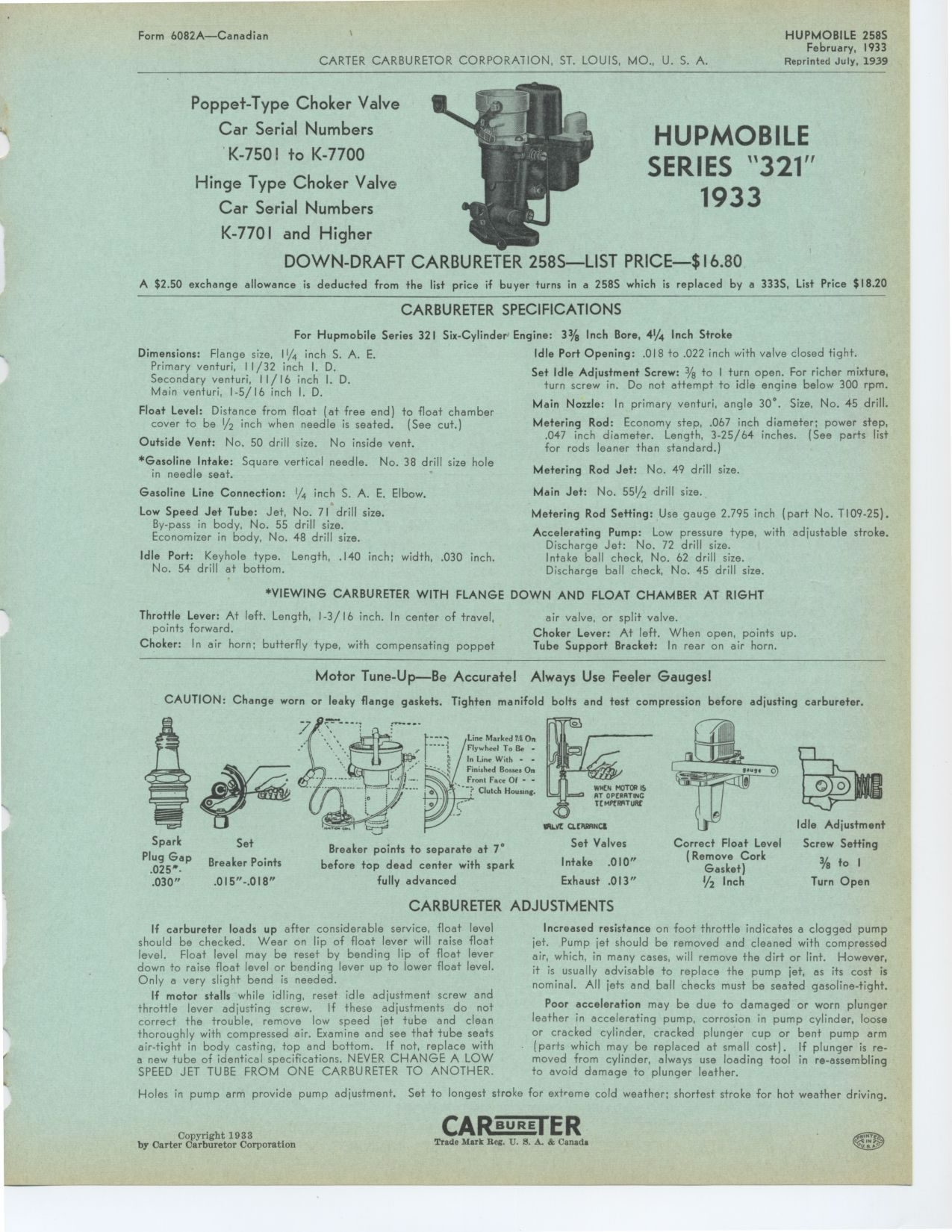
Poppet-Type Choker Valve
Car Serial Numbers
K-7501 to K-7700
Hinge Type Choker Valve
Car Serial Numbers
K-7701 and Higher
DOWN-DRAFT CARBURETER 258S—LIST PRICE—$16.80
A $2.50 exchange allowance is deducted from the list price if buyer turns
in a 258S which is replaced by a 333S, List Price $18.20
CARBURETER SPECIFICATIONS
For Hupmobile Series 321 Six-Cylinder Engine: 3% Inch Bore, 4¼ Inch
Stroke
Idle Port Opening: .018 to .022 inch with valve closed tight.
Set Idle Adjustment Screw: 3/8 to I turn open. For richer mixture, turn screw
in. Do not attempt to idle engine below 300 rpm.
Main Nozzle: In primary venturi, angle 30°. Size, No. 45 drill.
Metering Rod: Economy step, .067 inch diameter; power step, .047 inch diameter.
Length, 3-25/64 inches. (See parts list for rods leaner than standard.)
Metering Rod Jet: No. 49 drill size. Main Jet: No. 55½ drill size.
Metering Rod Setting: Use gauge 2.795 inch (part No. T109-25).
Accelerating Pump: Low pressure type, with adjustable stroke. Discharge Jet:
No. 72 drill size.
Intake ball check, No. 62 drill size.
Discharge ball check, No. 45 drill size.
*VIEWING CARBURETER WITH FLANGE DOWN AND FLOAT CHAMBER AT RIGHT
HUPMOBILE
SERIES "321"
1933
Dimensions: Flange size, 11/4 inch S. A. E. Primary venturi, 11/32 inch
I. D.
Secondary venturi, 11/16 inch I. D. Main venturi, 1-5/16 inch I. D.
Float Level: Distance from float (at free end) to float chamber cover
to be 1/2 inch when needle is seated. (See cut.)
Outside Vent: No. 50 drill size. No inside vent.
*Gasoline Intake: Square vertical needle. No. 38 drill size hole in needle
seat.
Gasoline Line Connection: 1/4 inch S. A. E. Elbow.
Low Speed Jet Tube: Jet, No. 71 drill size. By-pass in body, No. 55 drill
size. Economizer in body, No. 48 drill size.
Idle Port: Keyhole type. Length, .140 inch; width, .030 inch. No. 54
drill at bottom.
Throttle Lever: At left. Length, 1-3/16 inch. In center of travel, points
forward.
Choker: In air horn; butterfly type, with compensating poppet
air valve, or split valve.
Choker Lever: At left. When open, points up. Tube Support Bracket: In
rear on air horn.
Motor Tune-Up—Be Accurate! Always Use Feeler Gauges!
CAUTION: Change worn or leaky flange gaskets. Tighten manifold bolts
and test compression before adjusting carbureter.
Line Marked Ti On Flywheel To Be - In Line With - - Finished Bosses On
Front Fare Of - - -71 Clutch Housmg.
CLCARAHC1
Idle Adjustment
Spark Set Breaker points to separate at 7° Set Valves Correct Float Level
Screw Setting
Plug Gap (Remove Cork
Intake .010"
Breaker Points before top dead center with spark 3/e to I
.025". Gasket)
Exhaust .013"
.030" .015"-.018" fully advanced i/2 Inch Turn Open
CARBURETER ADJUSTMENTS
If carbureter loads up after considerable service, float level should
be checked. Wear on lip of float lever will raise float level. Float
level may be reset by bending lip of float lever down to raise float
level or bending lever up to lower float level. Only a very slight bend
is needed.
If motor stalls while idling, reset idle adjustment screw and throttle
lever adjusting screw. If these adjustments do not correct the trouble,
remove low speed jet tube and clean thoroughly with compressed air. Examine
and see that tube seats air-tight in body casting, top and bottom. If
not, replace with a new tube of identical specifications. NEVER CHANGE
A LOW SPEED JET TUBE FROM ONE CARBURETER TO ANOTHER.
Increased resistance on foot throttle indicates a clogged pump jet. Pump
jet should be removed and cleaned with compressed air, which, in many cases,
will remove the dirt or lint. However, it is usually advisable to replace
the pump jet, as its cost is nominal. All jets and ball checks must be
seated gasoline-tight.
Poor acceleration may be due to damaged or worn plunger leather in accelerating
pump, corrosion in pump cylinder, loose or cracked cylinder, cracked plunger
cup or bent pump arm (parts which may be replaced at small cost). If plunger
is re-moved from cylinder, always use loading tool in re-assembling to
avoid damage to plunger leather.
Holes in pump arm provide pump adjustment. Set to longest stroke for extreme
cold weather; shortest stroke for hot weather driving.
Copyright 1933
|