|
CARTER CARBURETOR CORPORATION, ST. LOUIS, MO., U. S. A.
Form 6502A—Canadian
OLDSMOBILE 523S
May, 1942
Reprinted May, 1944
OLDSMOBILE
SIX
SERIES 3500, 3600
1942
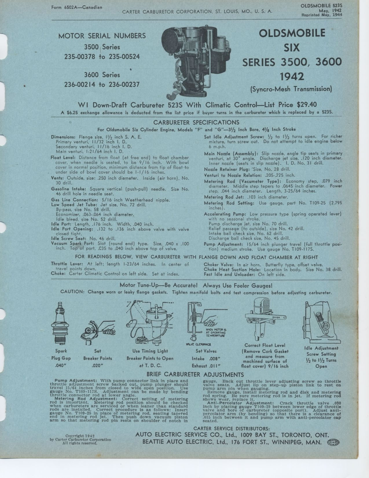
(Syncro-Mesh Transmission) WI Down-Draft Carbureter 523S With Climatic
Control—List
Price $29.40
A $6.25 exchange allowance is deducted from the list price if buyer turns
in the carbureter which is replaced by a 523S.
CARBURETER SPECIFICATIONS
For Oldsmobile Six Cylinder Engine, Models "F" and "G"—31/2
Inch Bore, 41/g Inch Stroke
Dimensions: Flange size, 11/2 inch S. A. E. Set Idle Adjustment Screw:
1/2 to 11/2 turns open. For richer
Primary venturi, 11/32 inch I. D. mixture, turn screw out. Do not attempt
to idle engine below
Secondary venturi, 11/16 inch I. D. 6 m.p.h. Main venturi, 1-21/64 inch
I. D.
Float Level: Distance from float (at free end) to float chamber cover,
when needle is seated, to be 9/ 16 inch. With bowl cover in normal position,
minimum distance from tip of float to under side of bowl cover should
be I-I/16 inches.
Vents: Outside, size: .250 inch diameter. Inside (air horn), No. 30 drill.
Gasoline Intake: Square vertical (push-pull) needle. Size No. 46 drill
hole in needle seat.
Gas Line Connection: 5/16 inch Weatherhead nipple. Low Speed Jet Tube:
Jet size, No. 72 drill.
By-pass, size No. 58 drill.
Economizer, .063-.064 inch diameter.
Idle bleed, size No. 52 drill.
Idle Port: Length, .176 inch. Width, .040 inch.
Idle Port Opening: .132 to .136 inch above valve with valve closed tight.
Idle Screw Seat: No. 46 drill.
Vacuum Spark Port: Slot (round end) type. Size, .040 x .100 inch. Top
of port, .C35 to .040 inch above top of valve.
FOR READINGS BELOW, VIEW CARBURETER WITH
Throttle Lever: At left; length 1-23/64 inches. In center of travel points
down.
Choke: Carter Climatic Control on left side. Set at index.
Motor Tune-Up—Be Accurate! Always Use Feeler Gauges!
CAUTION: Change worn or leaky flange gaskets. Tighten manifold bolts
and test compression before adjusting carbureter.
MOTOR SERIAL NUMBERS
3500 Series
235-00378 to 235-00524
3600 Series
236-00214 to 236-00237
Main Nozzle (Assembly): Slip nozzle, angle tip seats in primary
venturi, at 30° angle. Discharge jet size, .120 inch diameter.
Inner nozzle (seats in slip nozzle). I. D. No. 31 drill. Nozzle Retainer
Plug: "Size, No. 28 drill.
Venturi to Nozzle Relation: .205-.225 inch.
Metering Rod (Vacumeter Type): Economy step, .079 inch diameter. Middle
step tapers to .0645 inch diameter. Power step, .044 inch diameter. Length,
3-25/64 inches.
Metering Rod Jet: .103 inch diameter.
Metering Rod Setting: Use gauge, part No. T109-25 (2.795 inches).
Accelerating Pump: Low pressure type (spring operated lever) with no
seasonal stroke.
Pump discharge jet, size No. 70 drill.
Relief passage (to outside), size No. 42 drill.
Intake ball check size, No. 62 drill.
Discharge ball check size, No. 45 drill.
Pump Adjustment: 15/64 inch plunger travel (full throttle position) medium
stroke. Use gauge No. T109-117S.
FLANGE DOWN AND FLOAT CHAMBER AT RIGHT
Choker Valve: In air horn. Butterfly type, offset valve.
Choke Heat Suction Hole: Location in body. Size No. 38 drill. Fast Idle
and Unloader: On left side.
Spark Set
Plug Gap Breaker Points
.040" .020"Use Timing Light
Breaker Points to Open
at T. D. C.
VRLVC C eilRRNC1
Set Valves
Intake .008"
Exhaust .01 I"
Correct Float Level (Remove Cork Gasket
and measure from machined surface of float cover) 9/ 16 inch
Idle Adjustment
Screw Setting
1/2 to 11/2 Turns
Open
BRIEF CARBURETER ADJUSTMENTS
Pump Adjustment: With pump connector link in place and throttle adjustment
screw backed out, pump plunger should travel 15/64 inches from closed
to wide open position. Use gauge No. T109-117S. Adjustment can be made
by bending throttle connector rod at lower angle.
Metering Rod Adjustment: Correct setting of metering rod is important.
Metering rod position should be checked when carbureters are serviced
or when leaner than standard rods are installed. Correct procedure is
as follows: Insert gauge No. T109-25 in place of metering rod, seating
tapered end in metering rod jet. Then push down vacuum piston arm so
that metering rod pin rests on shoulder of notch ingauge. Back out throttle
lever adjusting screw so throttle valve seats. Adjust lip on step-up
piston link to rest on pump arm pin when gauging.
Remove gauge, install metering rod and disk and metering rod spring.
Be sure metering rod is in jet. If metering rod shows wear, replace it.
Anti-Percolator Adjustment: Crack throttle valve .030 inch by placing
gauge T109-29 between lower edge of throttle valve and bore of carbureter
(opposite port). Adjust anti-percolator arm (by bending) so that there
is a clearance of .015 inch between it and pump arm with anti-percolator
cap seated.
Copyright 1942
|