Oldcarburetors.com

Studebaker Carburetors : Studebaker Climatic Control WE Carburetor


Previous | Home | Next


Studebaker Climatic Control WE Carburetor

CARTER CARBURETOR CORPORATION, ST. LOUIS, MO., U. S. A. Page 3
CLIMATIC CONTROL ASSEMBLY

Slide fast idle cam assembly onto choke shaft. Install choke shaft into air horn and revolve cam to allow piston to slide freely into cylinder. Then lock fast idle cam spring ends around nib of cam and projecting nib of choke shaft assembly.
Install choke valve with trademark to top, seating valve before tightening screws. Valve must not bind in any position, but fall free of its own weight. Install fast idle link and choke trip lever. Place washer on choke connector rod assembly before attaching to fast idle link. Install spring and retainer.
Fast idle and unloader adjustments should be made at this point before the balance of climatic control is assembled. (Fig. 4) Install baffle plate and attaching screw. Install coil housing gasket. With choke wide open, hold coil housing with notch revolved one-quarter turn clockwise from index mark on housing. Place against housing and revolve counter clockwise to center index mark (532S), one point lean (6615) Lock in place with screws and retainer.
CARBURETER ADJUSTMENTS
FLOAT SETTING:
With bowl cover inverted and float lip resting on seated needle, distance from soldered seam of float to small projection on machined surface of bowl cover should be 1/4" (532S), 3/8" (661S). Adjustment should be made by bending lip of float lever.
After making float adjustment, adjust stops on float bracket so free end of float can move 1/2" plus or minus 1/32". PUMP ADJUSTMENT:
Good acceleration is dependent primarily on the amount of gasoline discharged through the pump jet. This quantity of pump discharge is controlled by the distance the pump plunger travels. Pump travel adjustment should be made each time the carbureter is serviced and must be made before metering rod or anti-percolator settings. Procedure is as follows:

(I ) Back out throttle lever adjusting screw to allow throttle valve to seat in bore of carbureter.

(2) Place pump travel gauge (tool T109-I 17S) on bcwl cover with lip of gauge extending over top of plunger shaft.

(3) Turn knurled nut of gauge until lip rests on top of plunger shaft, with throttle valve seated. Read number on gauge indicated by notch in knurled nut.

(4) Repeat operation number 3 with throttle valve wide open.

(5) The difference in the readings obtained at closed and at wide open throttle should be "17" (17/64"). ADJUSTMENT IS MADE BY BENDING THROTTLE CONNECTOR ROD AT LOWER ANGLE.
METERING ROD ADJUSTMENT:
Correct setting of metering rod is important and must be made when reassembling carbureter or when leaner thari standard rods are installed DO NOT DISTURB PUMP ADJUSTMENT.

Remove metering rod and disc, and install gauge T109-102 in place of metering rod, making sure lower end of gauge seats in metering rod jet. Back out throttle lever set screw so throttle valve seats in bore of carbureter. (Make sure fast idle cam does not hold throttle open. Throttle valve must be segated.) Press lightly on top of metering rod arm until upper lip of arm contacts pin in pump arm. There should be less flan .005" clearance between shoulder in notch of gauge and metering rod pin. Adjust by bending upper lip on metering rod arm. Use tool T109-105.
This carbureter provides an added economy measure by means of the second lip on metering rod arm which extends below pin in pump arm and should be adjusted as follows:

With throttle valve seated and finger pressing down on metering rod arm so that upper lip contacts pin on pump arm, adjust lower lip for 3/16" clearance between bottom of pump arm pin and upper surface of lower lip (use gauge
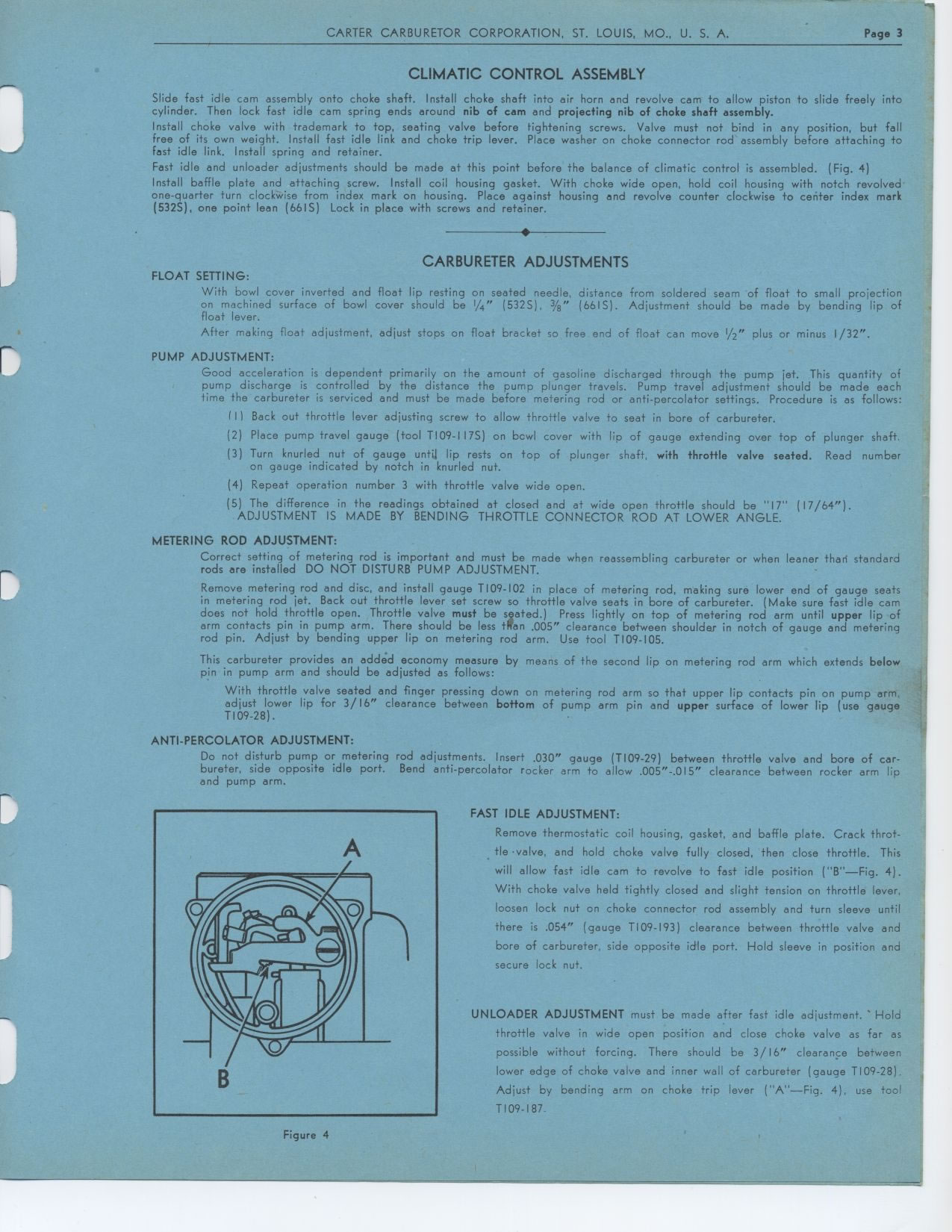
 T109-28).
ANTI-PERCOLATOR ADJUSTMENT:
Do not disturb pump or metering rod adjustments. Insert .030" gauge (T109-29) between throttle valve and bore of carbureter, side opposite idle port. Bend anti-percolator rocker arm to allow .005"-.015" clearance between rocker arm lip and pump arm.
FAST IDLE ADJUSTMENT:

Remove thermostatic coil housing, gasket, and baffle plate. Crack throttle .valve, and hold choke valve fully closed, then close throttle. This will allow fast idle cam to revolve to fast idle position ("B"—Fig. 4). With choke valve held tightly closed and slight tension on throttle lever, loosen lock nut on choke connector rod assembly and turn sleeve until there is .054" (gauge T109-193) clearance between throttle valve and bore of carbureter, side opposite idle port. Hold sleeve in position and secure lock nut.
UNLOADER ADJUSTMENT must be made after fast idle adjustment.' Hold throttle valve in wide open position and close choke valve as far as possible without forcing. There should be 3/16" clearance between lower edge of choke valve and inner wall of carbureter (gauge T109-28). Adjust by bending arm on choke trip lever ("A"—Fig. 4), use tool T109-187.
Figure 4