|
CARTER CARBURETOR CORPORATION, ST. LOUIS, MO., U. S. A.
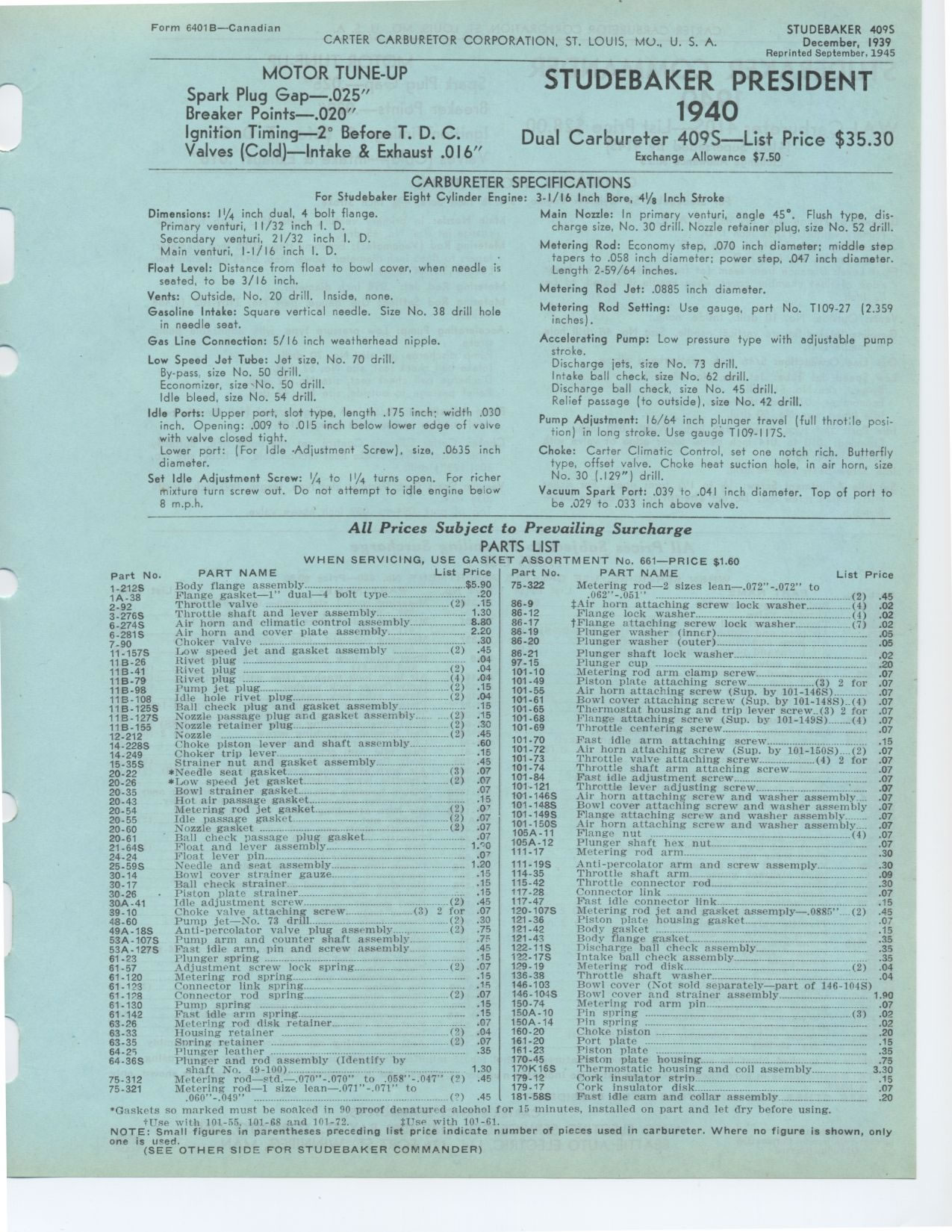
Form 6401B—Canadian
STUDEBAKER 409S
December, 1939
Reprinted September. 1945
MOTOR TUNE-UP
Spark Plug Gap—.025"
Breaker Points—.020"
Ignition Timing—2° Before T. D. C. Valves (Cold)—Intake & Exhaust
.016"
STUDEBAKER PRESIDENT 1940 Dual Carbureter 409S
Exchange Allowance $7.50
CARBURETER SPECIFICATIONS
For Studebaker Eight Cylinder Engine: 3-1/16 Inch Bore, 411/g Inch Stroke
Dimensions: II/4 inch dual, 4 bolt flange.
Primary venturi, 11/32 inch I. D.
Secondary venturi, 21/32 inch I. D.
Main venturi, I-I/16 inch I. D.
Float Level: Distance from float to bowl cover, when needle is seated, to
be 3/16 inch.
Vents: Outside, No. 20 drill. Inside, none.
Gasoline Intake: Square vertical needle. Size No. 38 drill hole in needle
seat.
Gas Line Connection: 5/16 inch weatherhead nipple.
Low Speed Jet Tube: Jet size, No. 70 drill.
By-pass. size No. 50 drill.
Economizer, size No. 50 drill.
Idle bleed, size No. 54 drill.
Idle Ports: Upper port, slot type, length .175 inch; width .030 inch. Opening:
.009 to .015 inch below lower edge of valve with valve closed tight.
Lower port: (For Idle -Adjustment Screw), size, .0635 inch diameter.
Set Idle Adjustment Screw: l/4 to 1/4 turns open. For richer mixture turn
screw out. Do not attempt to idle engine below 8 m.p.h.
Main Nozzle: In primary venturi, angle 45°. Flush type, discharge size,
No. 30 drill. Nozzle retainer plug, size No. 52 drill.
Metering Rod: Economy step, .070 inch diameter; middle step tapers to .058
inch diameter; power step, .047 inch diameter. Length 2-59/64 inches.
Metering Rod Jet: .0885 inch diameter.
Metering Rod Setting: Use gauge, part No. T109-27 (2.359 inches).
Accelerating Pump: Low pressure type with adjustable pump stroke.
Discharge jets, size No. 73 drill.
Intake ball check, size No. 62 drill.
Discharge ball check, size No. 45 drill.
Relief passage (to outside), size No. 42 drill.
Pump Adjustment: 16/64 inch plunger travel (full throt:le position) in long
stroke. Use gauge T109-117S.
Choke: Carter Climatic Control, set one notch rich. Butterfly type, offset
valve. Choke heat suction hole, in air horn, size No. 30 (.129") drill.
Vacuum Spark Port: .039 to .041 inch diameter. Top of port to be .029 to
.033 inch above valve.
All Prices Subject to Prevailing Surcharge PARTS LIST
WHEN SERVICING, USE GASKET ASSORTMENT No. 661—PRICE $1.60 PART NAME
List Price Part No. PART NAME
Body flange assembly $5 90 75-322 Metering rod—2 sizes lean—.072"-.072" to
Flange gasket—I" dual—4 bolt type 20 .062"-.051" (2)
Throttle valve (2) 15 86-9 $Air horn attaching screw lock washer (4)
Throttle shaft and lever assembly 1 30 86-12 Flange lock washer (4)
Air horn and climatic control assembly 8 80 86-17 Flange attaching screw
lock washer (7)
Air horn and cover plate assembly 2 20 86-19 Plunger washer (inner)
Choker valve 30 86-20 Plunger washer (outer)
Low speed jet and gasket assembly (2) 45 86-21 Plunger shaft lock washer
Rivet plug - . 04 04 97-15 Plunger cup ------°-
Rivet plug (2) 101-10 Metering rod arm clamp screw
Rivet plug (4) 04 101-49 Piston plate attaching screw (3) 2 for
lump jet plug (2) 1155 101-55 Air horn attaching screw (Sup. by 101-146S)_
Idle hole rivet plug (2) 101-61 Bowl cover attaching cheek plug and gasket
assembly _
15 101_65
10101--6868 T'L•cnge Thermostat housing g and d trip (Sup. by ]01-.(3)
2 fo for
r
lange attaching 2
Nozzle passage plug and gasket assembly- _(2 ..) achhing g screw (Sip SuP.
by lever 1001-149S)___...(4)
Nozzle retainer plug (2) 30 101-69 Throttle centering screw
Nozzle (2) 45 101-70 Fast idle arm attaching screw
Choke piston lever and shaft assembly _ .. 60
Choker trip lever 16 101-72 Air horn attaching screw (Sup• by 101-150S)._.(2)
101-73 Throttle valve attaching screw (4) 2 for
Strainer nut and gasket assembly"" _ . .45
101-74 Throttle shaft arm attaching screw
*Needle seat gasket (3) 07
*Low speed jet gasket---.---- _---- ------.--.-.--.(2) 07 101-84 Fast idle
adjustment screw
Bowl strainer gasket A7 101-121 Throttle lever adjusting screw
Hot air passage gasket 15 101-146S Air horn attaching screw and washer assembly
Metering rod jet gasket (2) 0' 101-148S Bowl cover attaching screw and washer
assembly
Idle passage gall: t_ (2) 0' 101-149S Flange attaching screw and washer assembly
Nozzle gasket _ _
_ (2) 07 101.150S Air horn attaching screw and washer assembly
Ball cheek 105A-11 Flange nut (4)
B
passage plug gasket 07 105A-12 Plunger shaft hex nut
Float and lever assembly 1 0
Float lever pin _ 2' 111-17 Metering and arm
Needle and seat assembly 1 20 111-19S Anti-percolator arm and screw assemply
Bowl cover strainer gauze 15 114-35 Throttle shaft arm
Ball check strainer 15 115-42 Throttle connector rod
Piston plate strainer 15 117.28 Connector link
Idle adjustment screw (2) 45 117-47 Fast idle connector link
Choke valve attaching screw (3) 2 for 07 120-107S Metering rod jet and gasket
assemply—.0885"_..(2)
Pump jet—No. 73 drill drill (2) 30 121-36 Piston plate housing gasket
Anti-percolator valve Plug assembly _- (2) 75 121-42 Body gasket - -
-----
------
I'ump arm and counter shaft assembly 7F 121-43 Body flange gasket
Fast idle arm, pin and screw assembly 45 122-11S Discharge ball check assembly
Plunger spring 15 1?2-17S Intake ball check assembly
Adjustment screw lock spring - (2) 07 129-19 Metering rod disk ..... (2)
Metering rod spring 15 136-38
Connector link spring 1.5 146-103
Connector rod spring- spring (2) 07 146.1045
Pump spring 15 150.74
Fast idle arm spring 15 150A-10
Metering rod disk retainer 07 150A-14
Housing retainer (2) .04 160-20
Spring retainer (2) .07 161-20
Plunger leather 35 161.23
Plunger and rod assembly (Identify by 170-45
shaft No. 49-100) _. .......... 1.30 17')K1SS
Metering rod—std.—.070"-.070" to .058"-.047" (2)
.45 179-12
Metering rod—1 size lean—.071"-.071" to 179-17
.060"-.049" (°) .45 . 181-58S
"Gaskets so marked must he soaked in 90 proof denatured alcohol for 15 minutes,
installed on part and let dry before using.
tree with 101-55. 101-68 and 161-72. $T'se with 101-61.
NOTE: Small figures in parentheses preceding list price indicate number of
pieces used in carbureter. Where no figure is shown, only one is ueed.
(SEE OTHER SIDE FOR STUDEBAKER COMMANDER)
Part No.
1-212S 1A-38 2-92 3-276S 6-274S 6-281S 7-90 11-157S
11 B-26 11 B-41 11B-79 11B-98 11B-108 11B-125S 11B-127S 11 B-155 12-212 14.228S
14-249 15-35S 20-22 20-26 20-35 20-43 20-54 20-55 20-60 20-61 21-64S 24-24
25-59S 30-14 30-17 30.26 30A-41 39-10 48.60 49A-18S 53A -107S 53A-127S 61.23
61-57 61.120 61-123 61.1.8 61.130 61-142 63-26 63-33 63-35 64-25 64-36S
75-312 75-321
Throttle shaft washer
Bowl cover (Not sold separately—part of 146-104S)
Bowl cover and strainer assembly 1.90
Metering rod arm pin 07
Pin spring (3) .02
Pin spring 02
Choke piston .........................................................-_--
.20
Port plate ° . .15
Piston plate 35
Piston plate housing 75
Thermostatic housing and coil assembly 3.30
Cork insulator strip 15
Cork insulator disk 07
Fast idle cam and collar assembly 20
List Price
|