|
CARTER CARBURETOR CORPORATION, ST. LOUIS, MO., U.S.A. Page
3
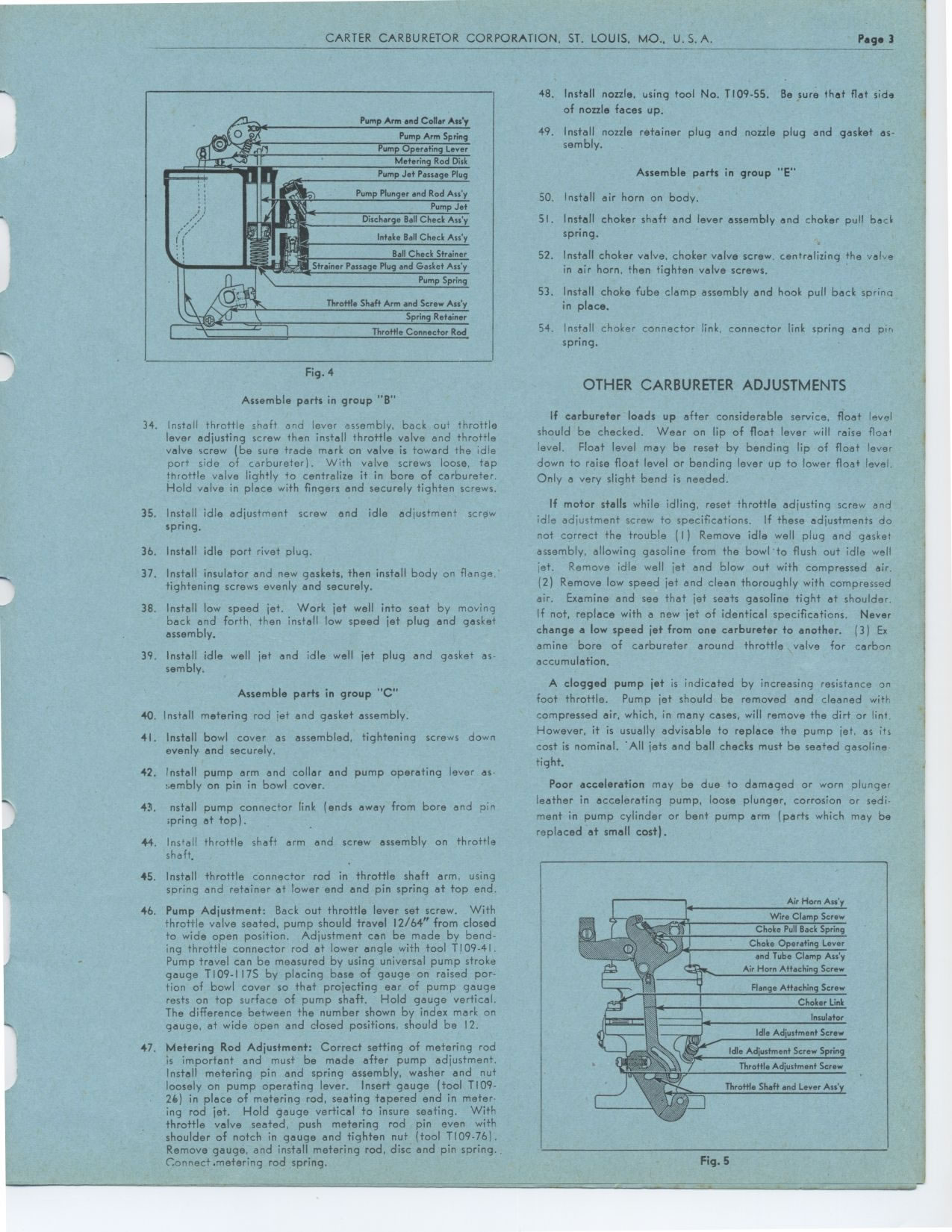
Pump Arm and Collor Ass y
dpt. Pump Arm Spring
O e'er Pump Operating Lever
.-
NMI IF Metering Rod Disk
see.' Pump Jet Passage Plug
~s
Pump Plunger and Rod Ass'y
Oii, Pump Jet
Discharge Ball Check
Ass'y
Intake Ball Check Ass'y
I, Ball Check Strainer
..k ~ yy-, Strainer Passage Plug and Gasket Ass'y
' \ Pump Spring
.-~
•
Throttle Shaft Arm and Screw Ass'y
Spring Retainer
Throttle Connector Rod
Fig. 4
Assemble parts in group "B"
34. Install throttle shaft and lever assembly, back out throttle lever adjusting
screw then install throttle valve and throttle valve screw (be sure trade mark
on valve is toward the idle port side of carbureter). With valve screws loose,
tap throttle valve lightly to centralize it in bore of carbureter. Hold valve
in place with fingers and securely tighten screws.
35. Install idle adjustment screw and idle adjustment screw spring.
36. Install idle port rivet plug.
37. Install insulator and new gaskets, then install body on flange, tightening
screws evenly and securely.
38. Install low speed jet. Work jet well into seat by moving back and forth,
then install low speed jet plug and gasket assembly.
39. Install idle well jet and idle well jet plug and gasket assembly.
Assemble parts in group "C"
40. Install metering rod jet and gasket assembly.
41. Install bowl cover as assembled, tightening screws down evenly and securely.
42. Install pump arm and collar and pump operating lever assembly on pin in bowl
cover.
43. nstall pump connector link (ends away from bore and pin ;pring at top).
44. Install throttle shaft arm and screw assembly on throttle shaft,
45. Install throttle connector rod in throttle shaft arm, using spring and retainer
at lower end and pin spring at top end.
46. Pump Adjustment: Back out throttle lever set screw. With throttle valve seated,
pump should travel 12/64" from closed to wide open position. Adjustment
can be made by bending throttle connector rod at lower angle with tool T109-41.
Pump travel can be measured by using universal pump stroke gauge T109-117S by
placing base of gauge on raised portion of bowl cover so that projecting ear
of pump gauge rests on top surface of pump shaft. Hold gauge vertical. The difference
between the number shown by index mark on gauge, at wide open and dosed positions.
should be 12.
47. Metering Rod Adjustment: Correct setting of metering rod is important and
must be made after pump adjustment. Install metering pin and spring assembly,
washer and nut loosely on pump operating lever. Insert gauge (tool T109-26) in
place of metering rod, seating tapered end in metering rod jet. Hold gauge vertical
to insure seating. With throttle valve seated, push metering rod pin even with
shoulder of notch in gauge and tighten nut (tool T109-76). Remove gauge, and
install metering rod, disc and pin spring.. Connect.metering rod spring.
48. Install nozzle, using tool No. T109.55. Be sure that flat side of nozzle
faces up.
49. Install nozzle retainer plug and nozzle plug and gasket assembly.
Assemble parts in group "E"
50. Install air horn on body.
51. Install choker shaft and lever assembly and choker pull back spring.
52. Install choker valve, choker valve screw. centralizing the vale in air
horn, then tighten valve screws.
53. Install choke fube clamp assembly and hook pull back sprino in place.
54. Install choker connector link, connector link spring and pir, spring.
OTHER CARBURETER ADJUSTMENTS
If carbureter loads up after considerable service, float level should be
checked. Wear on lip of float lever will raise float level. Float level may
be reset by bending lip of float lever down to raise float level or bending
lever up to lower float level. Only a very slight bend is needed.
If motor stalls while idling, reset throttle adjusting screw and idle adjustment
screw to specifications. If these adjustments do not correct the trouble
(I) Remove idle well plug and gasket assembly, allowing gasoline from the
bowl'to flush out idle well jet. Remove idle well jet and blow out with compressed
air. (2) Remove low speed jet and clean thoroughly with compressed air. Examine
and see that jet seats gasoline tight at shoulder. If not, replace with a
new jet of identical specifications. Never change a low speed jet from one
carburetor to another. (3) Ex amine bore of carbureter around throttle valve
for carbon accumulation.
A clogged pump jet is indicated by increasing resistance on foot throttle.
Pump jet should be removed and cleaned with compressed air, which, in many
cases, will remove the dirt or lint. However, it is usually advisable to
replace the pump jet. as its cost is nominal. 'All jets and ball checks must
be seated gasoline-tight.
Poor acceleration may be due to damaged or worn plunger leather in accelerating
pump, loose plunger, corrosion or sediment in pump cylinder or bent pump
arm (parts which may be replaced at small cost).
Fig. 5
Air Horn Ass'y
Wire Clamp Screw Choke Pull Back Spring Choke Operating Lever and Tube Clamp
Ass'y
Air Horn Attaching Screw
Flange Attaching Screw
Choker Link
Insulator Idle Adjustment Screw
Throttle Adjustment Screw Throttle Shaft and Lever Ass'y
|