Skip to: site menu | section menu | main content
UNIVERSAL JOINTS AND FRONT PROPELLER SHAFT
Universal Joints
There are three different types of universal joints used in the
1934 passenger cars and trucks. The first is the bolted trunnion
type and is used on Master passenger cars and % ton trucks. See
Fig. 134. The second type is the riveted trunnion type and is used
on Standard model passenger cars. See Fig. 135. The third is the
four arm spider type and is used on 1M ton trucks. See Fig. 136.
Universal Joint Specifications
1931 1932 1933 1934 1935
Type Steel Steel Steel Steel Steel
Yoke Yoke Yoke Yoke Yoke
Number of Bearings 4 4 4 4 4
Number of "U" Joints
132 Ton—131" WB 1 1 1 2 2
114 Ton—157" WB 2 2 2 2 2
Front Propeller Shaft
Length:
131" WB 1516" 15W
157" WB 2432" 2432" 2432" 41W 4116"
Grease Capacity of Front
Propeller Shaft:
131"WB %pt. %pt.
157" WB % pt. % pt. % pt. % pt. % pt.
Universal Joint (Master Passenger Cars and Ton Trucks)
The universal joint used on the Master passenger cars and % ton
trucks is simple in construction and operation. A glance at Fig.
134 shows this simple construction and the relative position of
all of the parts of this unit. The front and rear yokes are made
from drop forgings heat treated to provide strength. These yokes
have splines cut in the inside hole to fit on the end of the transmission main
shaft and the end of the propeller shaft. The ends of the yokes, to which the
trunnion bearings are assembled, are carefully machined and ground to provide
a smooth bearing surface for the trunnion bearings. The trunnion bearings are
held in place by two rings and four bolts and nuts.
The oil seal at the rear of the universal joint ball is of the adjustable type.
The sealing is accomplished by a felt packing ring which is pressed against the
end of the propeller shaft housing, with two steel washers, one on each side
of the packing. Adjustment, to compensate for wear, is made by turning the sleeve
with a special tool assuring a perfect seal at this point under all conditions.
To remove this universal joint, remove the speedometer gear and shaft from the
joint ball retainer, to eliminate the possibility of stripping
61the teeth of these gears. Separate the joint by removing the cap screws holding
the retaining collar to the ball retainer and slide the ball back onto the propeller
shaft housing. Remove the nuts from the bolts holding the joint rings together
and split the joint. Remove the cap screw holding the front yoke to the end of
the transmission main shaft with a special long shank wrench. Remove the rear
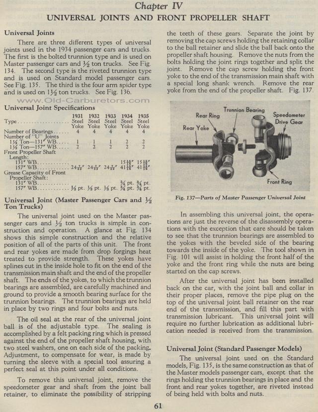
yoke from the end of the propeller shaft. Fig. 137.
Fig. 137— Parts of Master Passenger Universal Joint
In assembling this universal joint, the operations are just the reverse of the
disassembly operations with the exception that care should be taken to see that
the trunnion bearings are assembled to the yokes with the beveled side of the
bearing towards the inside of the yoke. The tool shown in Fig. 101 will assist
in holding the front half of the yoke and the front ring while the nuts are being
started on the cap screws.
After the universal joint has been installed back on the car, with the joint
ball and collar in their proper places, remove the pipe plug on the top of the
universal joint ball retainer on the rear end of the transmission, and fill this
part with transmission lubricant. This universal joint will require no further
lubrication as additional lubrication needed is received from the transmission.
Universal Joint (Standard Passenger Models)
The universal joint used on the Standard models, Fig. 135, is the same construction
as that of the Master models passenger cars, except that the rings holding the
trunnion bearings in place and the front and rear yokes together, are riveted
instead of being held with bolts and nuts.
