Skip to: site menu | section menu | main content
this part with transmission lubricant. This joint will require
no further lubrication as additional lubrication is received from
the transmission. Through the lubrication or high pressure fittings
on the side of the front propeller shaft assembly, fill this part with transmission
lubricant. Additional lubricant should be put in this joint at the regular 1000
mile lubrication periods.
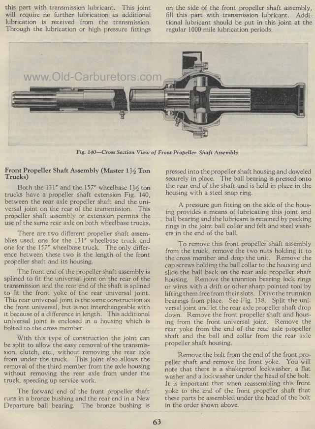
Cross Section View of Front Propeller Shaft Assembly
Front Propeller Shaft Assembly (Master 1 1/2 Ton Trucks)
Both the 131" and the 157" wheelbase 1M ton trucks have
a propeller shaft extension Fig. 140, between the rear axle propeller
shaft and the universal joint on the rear of the transmission.
This propeller shaft assembly or extension permits the use of the
same rear axle on both wheelbase trucks.
There are two different propeller shaft assemblies used, one for
the 131" wheelbase truck and one for the 157" wheelbase
truck. The only difference between these two is the length of the
front propeller shaft and its housing.
The front end of the propeller shaft assembly is splined to fit
the universal joint on the rear of the transmission and the rear
end of the shaft is splined to fit the front yoke of the rear universal
joint. This rear universal joint is the same construction as the
front universal, but is not interchangeable with it because of
a difference in length. This additional universal joint is enclosed
in a housing which is bolted to the cross member.
With this type of construction the joint can be split to allow
the easy removal of the transmission, clutch, etc., without removing
the rear axle from under the truck. This joint also allows the
removal of the third member from the axle housing without removing
the rear axle from under the truck, speeding up service work.
The forward end of the front propeller shaft runs in a bronze bushing
and the rear end in a New Departure ball bearing. The bronze bushing
is
63pressed into the propeller shaft housing and doweled securely
in place. The ball bearing is pressed onto the rear end of the
shaft and is held in place in the housing with a steel snap ring.
A pressure gun fitting on the side of the housing provides a means
of lubricating this joint and ball bearing and the lubricant is
retained by packing rings in the joint ball collar and felt and
steel washers in the end of the ball.
To remove this front propeller shaft assembly from the truck, remove
the two nuts holding it to the cross member and drop the unit.
Remove the cap screws holding the ball collar to the housing and
slide the ball back on the rear axle propeller shaft housing. Remove
the trunnion bearing lock rings or wires with a drift or other
sharp pointed tool by lifting them free from their slots. Drive
the trunnion bearings from place. See Fig. 138. Split the universal
joint and let the rear axle propeller shaft drop down. Remove the
front propeller shaft and housing from the front universal joint.
Remove the rear yoke from the end of the rear axle propeller shaft
and the ball and collar from the rear axle propeller shaft housing.
Remove the bolt from the end of the front propeller shaft and remove
the front yoke. You will note that there is a shakeproof lockwasher,
a flat washer and a lockwasher under the head of the bolt. It is
important that when reassembling this front yoke to the end of
the front propeller shaft that these parts be assembled under the
head of the bolt in the order shown above.
