Skip to: site menu | section menu | main content
1935 Chevy Steering Geometry
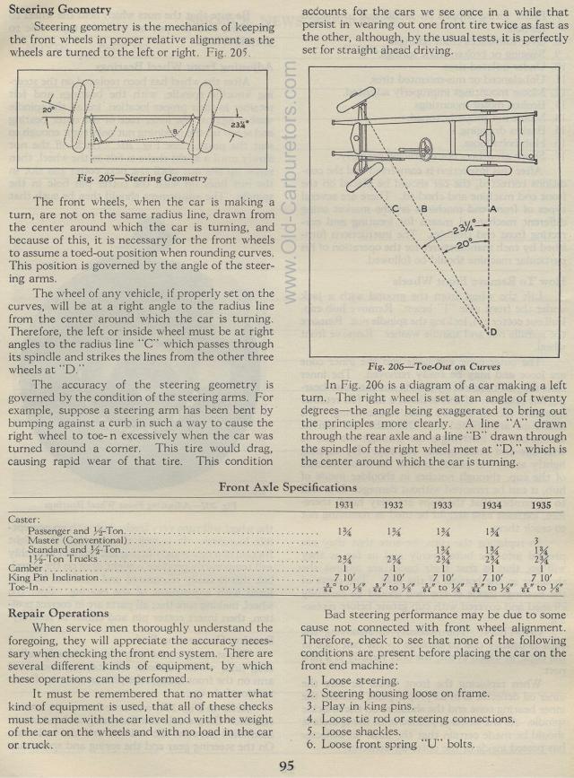
Steering geometry is the mechanics of keeping the front wheels in proper relative alignment as the wheels are turned to the left or right. Fig. 205.
Steering Geometry
The front wheels, when the car is making a turn,
are not on the same radius line, drawn from the center around which
the car is turning, and because of this, it is necessary for the
front wheels to assume a toed-out position when rounding curves.
This position is governed by the angle of the steering arms.
The wheel of any vehicle, if properly set on the curves, will be
at a right angle to the radius line from the center around which
the car is turning. Therefore, the left or inside wheel must be
at right angles to the radius line "C" which passes through
its spindle and strikes the lines from the other three wheels at "D."
The accuracy of the steering geometry is governed by the condition
of the steering arms. For example, suppose a steering arm has been
bent by bumping against a curb in such a way to cause the right
wheel to toe- n excessively when the car was turned around a corner.
This tire would drag, causing rapid wear of that tire. This conditionaccounts
for the cars we see once in a while that persist in wearing out
one front tire twice as fast as the other, although, by the usual
tests, it is perfectly set for straight ahead driving.
Fig. 206— Toe-Out on Curves
In Fig. 206 is a diagram of a car making a left turn. The right
wheel is set at an angle of twenty degrees the angle being exaggerated
to bring out the principles more clearly. A line "A" drawn
through the rear axle and a line "B" drawn through the
spindle of the right wheel meet at "D," which is the
center around which the car is turning.
Front Axle Specifications
1931 1932 1933 1934 1935 Use page image below
to read this table.
Caster: I 1% 134 1%
Passenger and u-Ton
Master (Conventional) 3
Standard and ?,2-Ton 1% 1% 1%
11,2'-Ton Trucks 2% 2% 2% 2% 2%
Camber 1 1 1 1 1
King Pin Inclination 7 10' 7 10' 7 10' 7 10' 7 10'
Toe-In sue° to 3 " 4„ to 18, A" to ;8a s4" tow fi4" to
M"
Repair Operations
When service men thoroughly understand the foregoing, they will appreciate the
accuracy necessary when checking the front end system. There are several different
kinds of equipment, by which these operations can be performed.
It must be remembered that no matter what kind of equipment is used, that all
of these checks must be made with the car level and with the weight of the car
on the wheels and with no load in the car or truck.
95
Bad steering performance may be due to some cause not connected with front wheel
alignment. Therefore, check to see that none of the following conditions are
present before placing the car on the front end machine:
1. Loose steering.
2. Steering housing loose on frame.
3. Play in king pins.
4. Loose tie rod or steering connections.
5. Loose shackles.
6. Loose front spring "U" bolts.
