Skip to: site menu | section menu | main content
assembled between the rod end and ball seat. This is very important as the springs assembled in this manner relieve road shock from the steering gear in both directions.
Steering Connecting Rod Assembly
To properly adjust this steering connecting rod:
I. Remove cotter pins.
2. Screw plugs in tight and back off to first cotter pin hole.
3. Insert and clinch cotter pins.
4. Lubricate both ends of tie rod.
Taking Lost Motion Out of Steering Connecting Rod
Remove the cotter pin from the end of the steering connecting rod.
See Fig. 209.
Fig. 209— Adjusting Steering Connecting Rod
Remove screw plug and all internal parts.
Clean the rod ends and inside parts \~ ith gasoline.
Lubricate the ball seat surfaces with heavy oil or light grease
and reinstall.
With a screw driver placed in the slot in the screw plug tighten
until parts are firmly seated and spring compressed solid, then
back off to first cotter pin hole. After this is done, all lost
motion will be removed. Be sure to lock the plug with cotter pin
and clinch over. Failure to do so may lead to a serious accident.
Lubricate both tie rod ends.
97Front Axle Tie Rod
The front axle tie rod is of the ball, seat and spring type, similar
to the steering connecting rod construction.
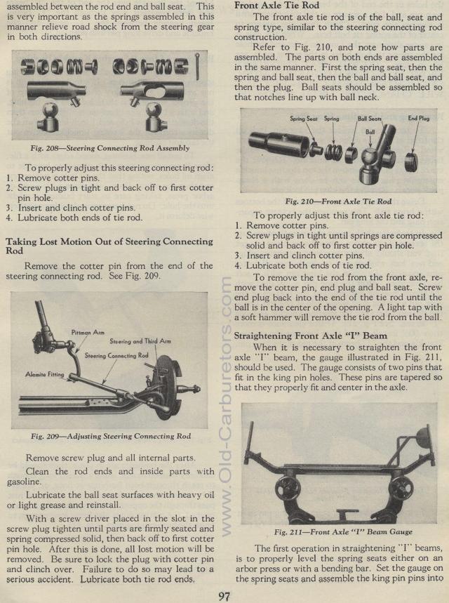
Refer to Fig. 210, and note how parts are assembled. The parts
on both ends are assembled in the same manner. First the spring
seat, then the spring and ball seat, then the ball and ball seat,
and then the plug. Ball seats should be assembled so that notches
line up with ball neck.
Fig. 210— Front Axle Tie Rod
To properly adjust this front axle tie rod:
1. Remove cotter pins.
2. Screw plugs in tight until springs are compressed solid and
back off to first cotter pin hole.
3. Insert and clinch cotter pins.
4. Lubricate both ends of tie rod.
To remove the tie rod from the front axle, re-move the cotter pin,
end plug and ball seat. Screw end plug back into the end of the
tie rod until the ball is in the center of the opening. A light
tap with a soft hammer will remove the tie rod from the ball.
Straightening Front Axle "I" Beam
When it is necessary to straighten the front axle "I" beam,
the gauge illustrated in Fig. 211, should be used. The gauge consists
of two pins that fit in the king pin holes. These pins are tapered
so that they properly fit and center in the axle.
Fig. 211— Front Axle "I" Beam Gauge
The first operation in straightening "I" beams, is to
properly level the spring seats either on an arbor press or with
a bending bar. Set the gauge on the spring seats and assemble the
king pin pins into
Spring Seat Spring Ball Sean
End Plug
