Skip to: site menu | section menu | main content
1935 Chevy Clutch Repair
the splines in the clutch disc. The use of these guide pins during this operation will support the trans-mission and prevent damage to the clutch disc through springing. Remove the transmission.
Disconnect the clutch pedal pull back spring and the retaining
spring from the end of the clutch and brake pedal shaft. Remove
the clutch pedal. Remove the special cap screw holding the throwout
fork to the flywheel housing. Two wrenches are necessary for this
operation, one to hold the swivel on the fork, and one to remove
the special cap screw. Remove the throwout fork and bearing assembly.
Force the springs holding the throwout sleeve to the throwout levers
over the ends of the levers and remove the sleeve. Remove the nine
cap screws, holding the clutch cover to the flywheel, backing off
each screw one turn at a time until the tension is relieved from
the cover. Remove the clutch and clutch disc.
Clutch Pilot Bearing
The clutch pilot bearing is a special oil shield type New Departure
ball bearing. This bearing needs attention only when the clutch
is removed from the car, at which time it should be removed,
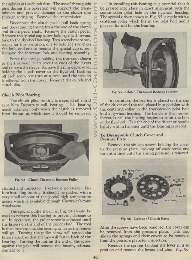
Fig. 94— Clutch Throwout Bearing Puller
cleaned and inspected. Replace if necessary. Be-fore installing
bearing, it should be packed with a very small amount of the special
high temperature grease which is available through Chevrolet's
zone warehouses.
The special puller shown in Fig. 94 should be used to remove this
bearing to prevent damage to it. In operation, the puller screw
is adjusted until the fingers on the end of the puller close. The
tool is then inserted into the bearing as far as the fingers will
go. Turning the puller screw will spread the fingers apart so that
the tips will fasten back of the bearing. Turning the nut on the
end of the screw against the yoke will remove this bearing without
damage to it.
In installing this bearing it is essential that it be pressed into
place in exact alignment with the transmission pilot hole in the
flywheel housing. The special driver shown in Fig. 95 is made with
a centering collar which fits in the pilot hole and a pilot on
its end for the bearing.
Fig. 95— Clutch Throwout Bearing Inserter
In operation, the bearing is placed on the end of the driver and
the tool placed into position with the centering collar in the
transmission pilot hole in the flywheel housing. The handle is
then moved forward until the bearing begins to enter the hole in
the flywheel. Tap the end of the driver or handle lightly with
a hammer until the bearing is seated.
To Disassemble Clutch Cover and Pressure Plate
Remove the six cap screws holding the cover to the pressure plate,
backing off each screw one turn at a time until the spring pressure
is relieved.
Fig. 96— Layout of Clutch Parts
After the screws have been removed, the cover can be removed from
the pressure plate. This also allows the springs and their covers
to be removed from the pressure plate for inspection.
Remove the springs holding the lever pins in position and remove
the levers and pins. Fig. 96.