Skip to: site menu | section menu | main content
Replacement of Transmission
These operations are just the reverse of the removal operations.
The tool shown in Fig. 101 can be used to hold the universal
joint rings in position while assembling the nuts.
Fig. 101— Universal Joint Holding Tool
Clutch Pedal Adjustment
There are two very important adjustments to the clutch pedal. The
first is for obtaining the proper clearance between the clutch
pedal and the floor board and the second for obtaining 1" of
pedal travel before the clutch begins to disengage. These two adjustments
compensate for wear of the clutch parts, and, if these two operations
are performed when necessary, long, trouble-free clutch operation
can be expected.
Fig. 102— Pedal Stop— Passenger
Cars
To obtain %" clearance between the clutch pedal and the floor
board, loosen nuts "A" and "B" in Fig. 102,
and move the pedal stop either forward or backward until the clutch
pedal clears the floor board %".
NOTE— The "X" mark on the clutch cover should be
lined up as near as is possible with the "X" mark on
the flywheel. These "X" marks are balance marks.
Place clutch pilot tool, Fig. 99, into position. This tool properly
lines up the disc so that when the transmission is assembled the
splines on the main drive gear shaft will line up and enter easily
the splines in the clutch disc.
Assemble the nine cap screws holding the clutch cover to the flywheel,
tightening each one one turn at a time until the cover is assembled
into position. Remove the clutch disc aligning tool. Assemble throwout
bearing sleeve.
Clutch Lever Heights
It is very important that the clutch levers be of the same height
to assure correct clutch operation. In addition to the clutch levers
being the same height, the maximum run-out of the clutch throw-out
bearing plate should not exceed .020",
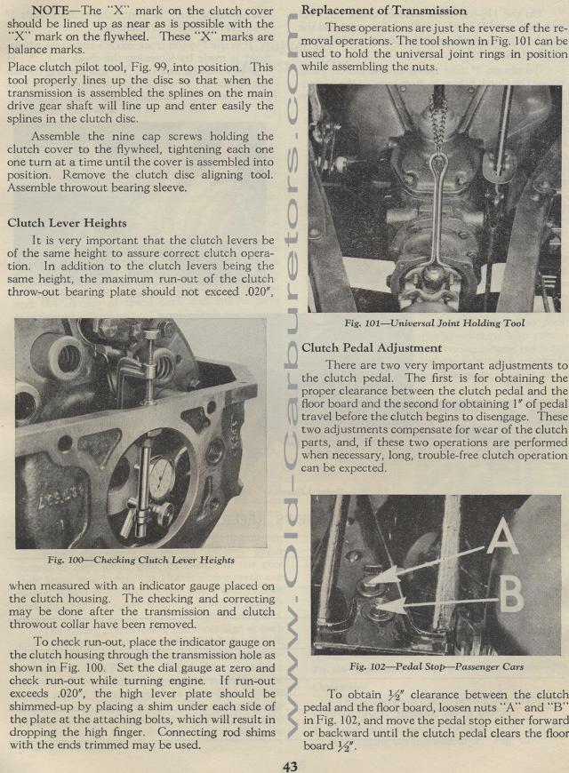
Fig. 100— Checking Clutch Lever Heights
when measured with an indicator gauge placed on the clutch housing.
The checking and correcting may be done after the transmission
and clutch throwout collar have been removed.
To check run-out, place the indicator gauge on the clutch housing
through the transmission hole as shown in Fig. 100. Set the dial
gauge at zero and check run-out while turning engine. If run-out
exceeds .020", the high lever plate should be shimmed-up by
placing a shim under each side of the plate at the attaching bolts,
which will result in dropping the high finger. Connecting rod shims
with the ends trimmed may be used.
