Skip to: site menu | section menu | main content
KNEE ACTION OR INDEPENDENT
FRONT WHEEL SUSPENSION
MASTER PASSENGER CAR MODELS
Construction
In the 1934 Master passenger car models, the front wheels are popularly
known as "Knee Action Wheels "or" Independently
Sprung Front Wheels."
This design allows the wheel to move straight up or down in following
irregularities of the road. Whether these irregularities be raised
obstructions or chuck holes, the shock will not be transmitted
to the car or passengers.
In this construction, a king pin support is attached to the front
end of a rigid frame with special bolts and the front wheel and
spring housing is mounted on king pins at the end of this support.
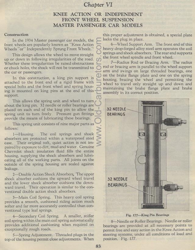
This allows the spring unit and wheel to turn about the king pin.
32 needle or roller bearings are placed on each end of the king
pin to allow the spring unit to turn freely. Pressure gun fittings
provide the means of lubricating these bearings.
This spring unit consists of nine major parts as follows:
1— Housing. The coil springs and shock absorbers
are protected within a waterproof steel case. Their original soft,
quiet action is not impaired by exposure to dirt, mud and water.
Genuine Chevrolet shock insulation fluid fills the entire housing,
supplying the shock absorbers and lubricating all of the working
parts. All joints on the outside of the spring housing are sealed
against leakage.
2— Double Action Shock Absorbers,. The upper
shock absorber cushions the upward wheel travel and the lower shock
absorber cushions the down-ward travel. Their operation is similar
to the conventional double action shock absorbers.
3— Main Coil Spring. This heavy coil spring
provides a smooth, cushioned riding action much softer and far
more accurately controlled than conventional type leaf springs.
4— Secondary Coil Spring. A smaller, stiffer
coil spring within the main coil spring automatically provides
additional cushioning when required on exceptionally rough roads.
5— Spring Adjustment. Threaded plugs in
the top of the housing permit close adjustments, When
this proper adjustment is obtained, a special plate locks the plug
in place.
6 Wheel Support Arm. The front end of this heavy
drop-forged alloy steel arm operates the coil springs and shock
absorbers. The rear end supports the front wheel spindle and front
wheel.
7— Radius Rod or Bracing Arm. The radius
rod or bracing arm is parallel to the wheel support arm and swings
on large threaded bearings, one on the brake flange plate and one
on the spring housing, bracing the wheel and permitting the wheel
to travel only straight up and down and maintaining the brake flange
plate and brake assembly in its correct position.
Fig. 177— King Pin Bearings
8— Needle or Roller Bearings. Needle or roller bearings are
provided at all necessary points to permit free and easy action
in the Knee Action and steering systems, under all conditions of
load and position. Fig. 177.
