Skip to: site menu | section menu | main content
all the way back, strike the plunger a hard fast blow with a hammer.
See Fig. 192. The impact through pressure will blow the plug out.
After plugs have been removed, remove the king pins.
Removing Expansion Plug
During the operation of removing the king pin, the needle or roller bearings will begin to fall out of the lower support boss and when the king pin has been removed be sure and pick out the remainder bearings from the lower support boss and
Fig. 193— Replacing King Pin
all of the bearings from the upper support boss. After this has
been done the front wheel suspension or spring unit can be removed
or lifted from the king pin support.
To reassemble the front spring unit to the king pin support the
following operations are necessary:
89
Assemble the front spring unit to the king pin support and start
the king pin in at the bottom being sure that the longest end of
the king pin, from the slot, is at the top and that the slot in
the king pin, lines up with the lock pin hole. Fig. 193.
Tap the king pin thrust bearing into place using a soft head hammer
for this operation. The king pin thrust bearing must always be
assembled between the upper support boss and the top of spring
housing or steering knuckle with the dust shield side towards the
top.
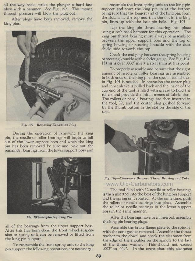
Check the end play between the spring housing or steering knuckle
with a feeler gauge. See Fig. 194. If this is over .006" insert
a steel shim at this point.
To properly assemble and be sure that the right amount of needle
or roller bearings are assembled in both ends of the king pins
the special tool shown in Fig. 195 is needed. In operation the
center plug and inner sleeve is pulled back and the inside of the
cup end of the tool is filled with grease to hold the rollers and
provide the initial means of lubrication The rollers or needle
bearings are then inserted in the tool, 32, and the center plug
pushed forward by the thumb button in the slot on the side of the
tool.
Fig. 194— Clearance Between Thrust Bearing and Yoke
The tool filled with 32 needle or roller bearings is then inserted
into the boss of the king pin support and the spring unit rotated.
At the same time, push the rollers or needle bearings into place.
Assemble the roller or needle bearings in the lower support boss
in the same manner.
After the bearings have been inserted, assemble the king pin bearing
plugs.
Assemble the brake flange plate to the spindle, with the cork gasket
removed. Assemble the thrust washer to the dowel and check the
clearance from the edge of the shoulder on the spindle to the face
of the thrust washer. This should not exceed .002" to .004".
In the event that this clearance
