Skip to: site menu | section menu | main content
These needle bearings are quite like a straight roller bearing without cages, and using rollers of comparatively small diameter —.093". The bearing races, instead of being a part of the bearing itself, are the ground surfaces of the two parts between which the needle bearings are placed. In some cases the needles are held from end movement by an adjoining part butting against their ends. In either case with clearance to prevent binding. The name is derived from the comparatively small size of the rollers.
These needle bearings are quite like a straight roller
bearing without cages, and using rollers of comparatively small
diameter —.093". The bearing races, instead of being
a part of the bearing itself, are the ground surfaces of the two
parts between which the needle bearings are placed. In some cases
the needles are held from end movement by an adjoining part butting
against their ends. In either case with clearance to prevent binding.
The name is derived from the comparatively small size of the rollers.
Operation
As the wheel moves upward, the front end of the wheel support arm
contacts the main spring which takes the wheel load and cushions
the movement of the wheel. This main spring functions for FA" of
the upward movement of the wheel and arm, after which the small
inner "bottoming" spring is compressed, building up the
spring pressure and cushioning and stopping the shock from being
transmitted to the car and occupants. At the same time the front
end of the wheel support arm contacts the upper shock absorber,
which also cushions the movement of the wheel.
The lower shock absorber cushions the wheel and the support arm
on its downward movement. The main coil spring pressure forces
the wheel downward and forces it to follow the road.
Knee Action Specifications
1934 1935
King Pin Caster 0 0
(Caster effect at wheel is obtained by trailing center of wheel
behind center of king pin.)
Camber 1° %°
King Pin Angle 7° 7%°
Toe-In. i 2,
-2v"
• 16 to 32 16 to a
32
Geometry (Toe-Out) 20°–23 ° 20°–23 ° Wheel Setting — Bottom
of king pin
support to bottom of brake flange
plate 5 /L, 5%//
NOTE— On Master knee-action models King Pin Caster, Wheel Camber and King
Pin Angle checks must be made from the Frame with the approved Chevrolet Gauge,
while weight is on spindles.
Care
At least every 1000 miles the level of the shock insulation fluid in the spring
housing should be checked and the proper amount of Genuine Chevrolet Shock Insulation
Fluid added to bring the level up to and even with the filler plug on the front
of the housing. Genuine Chevrolet shock insulation fluid is recommended for this
purpose as it will retain its fluid characteristics when the temperature is as
low as 40 degrees below zero. This fluid is carried in stock at all Chevrolet
zone warehouses.
Pressure gun fittings on the king pin and radius rod provide the means of lubricating
these points. They should be lubricated with chassis
84lubricant every 1000 miles. At least every 5,000 miles the front spindle bushing
should be lubricated. To do this, remove the plug at the inner end of the spindle
and pack the reservoir with a lubricant such as vaseline or petrolatum. Passages
from the reservoir carry the lubricant through the spindle to the bearing surface.
Pressure should not be used at this point.
Checking Knee-Action Unit
In making checks of the knee-action unit, the car should be jacked-up,
the front wheels and bearings removed from the spindles and the
king pin roller bearings checked for wear. I f worn they should
be replaced as described later in this chapter. The ball and
socket joints, steering arm nuts and king pin support to frame
bolts should be checked for looseness. The steering gear should
be checked for adjustment. Any of these conditions should be
corrected before making any checks on the front end.
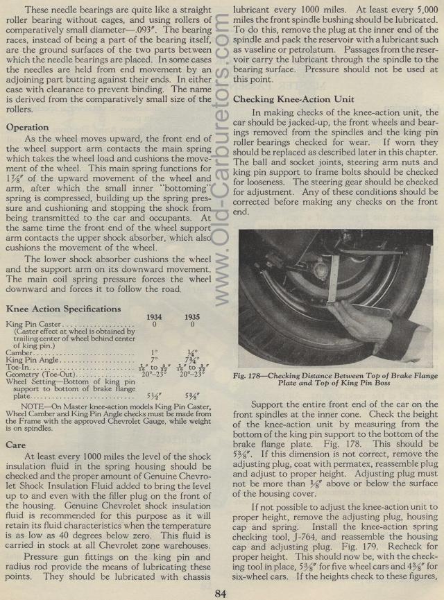
Fig. 178— Checking Distance Between Top of Brake Flange
Plate and Top of King Pin Boss
Support the entire front end of the car on the front spindles at
the inner cone. Check the height of the knee-action unit by measuring
from the bottom of the king pin support to the bottom of the brake
flange plate. Fig. 178. This should be 5%". If this dimension
is not correct, remove the adjusting plug, coat with permatex,
reassemble plug and adjust to proper height. Adjusting plug must
not be more than %" above or below the surface of the housing
cover.
If not possible to adjust the knee-action unit to proper height,
remove the adjusting plug, housing cap and spring. Install the
knee-action spring checking tool, J-764, and reassemble the housing
cap and adjusting plug. Fig. 179. Recheck for proper height. This
should now be, with the checking tool in place, SW for five wheel
cars and 4%" for six-wheel cars. If the heights check to these
figures,
