Skip to: site menu | section menu | main content
exceeds these limits, place a shim between the hub of the brake flange plate and the thrust washer. After this clearance is obtained, remove the thrust washer and the brake flange plate.
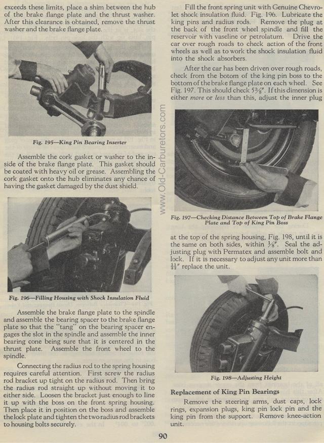
King Pin Bearing Inserter
Assemble the cork gasket or washer to the in-side of the brake flange plate. This gasket should be coated with heavy oil or grease. Assembling the cork gasket onto the hub eliminates any chance of having the gasket damaged by the dust shield.
Fig. 196— Filling Housing with Shock Insulation Fluid
Assemble the brake flange plate to the spindle and assemble the
bearing spacer to the brake flange plate so that the "tang" on
the bearing spacer en-gages the slot in the spindle and assemble
the inner bearing cone being sure that it is centered in the thrust
plate. Assemble the front wheel to the spindle.
Connecting the radius rod to the spring housing requires careful
attention. First screw the radius rod bracket up tight on the radius
rod. Then bring the radius rod straight up without moving it to
either side. Loosen the bracket just enough to line it up with
the boss on the front spring housing. Then place it in position
on the boss and assemble the lock plate and tighten the two radius
rod brackets to housing bolts securely.
90
Fill the front spring unit with Genuine Chevrolet shock insulation
fluid. Fig. 196. Lubricate the king pins and radius rods. Remove
the plug at the back of the front wheel spindle and fill the reservoir
with vaseline or petrolatum. Drive the car over rough roads to
check action of the front wheels as well as to work the shock insulation
fluid into the shock absorbers.
After the car has been driven over rough roads, check from the
botom of the king pin boss to the bottom of the brake flange plate
on each wheel. See Fig. 197. This should check 5 3/8 ". If
this dimension is either more or less than this, adjust the inner
plug
Checking Distance Between Top of Brake Flange
Plate and Top of King Pin Boss
at the top of the spring housing, Fig. 198, until it is the same
on both sides, within %". Seal the adjusting plug with Permatex
and assemble bolt and lock. I f it is necessary to adjust any unit
more than 3s" replace the unit.
Fig. 198— Adjusting Height
Replacement of King Pin Bearings
Remove the steering arms, dust caps, lock rings, expansion plugs,
king pin lock pin and the king pin from the support. Remove knee-action
unit.
