Skip to: site menu | section menu | main content
Willys Station Sedan Series "663" 1948
Form 6579—Canadian
WILLYS 645S August, 1948
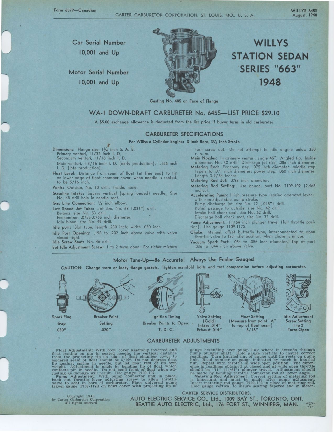
Casting No. 485 on Face of Flange
Car Serial Number
10,001 and Up
Motor Serial Number
10,001 and Up
WILLYS STATION SEDAN SERIES "663" 1948
WA-I DOWN-DRAFT CARBURETER No. 645S—LIST PRICE $29.10
A $5.00 exchange allowance is deducted from the list price if buyer turns
in old carbureter.
CARBURETER SPECIFICATIONS
For Willys 6 Cylinder Engine:
I
Dimensions: Flange size, 11/4 inch S. A. E.
Primary venturi, 11/32 inch I. D.
Secondary venturi, 11/16 inch I. D.
Main venturi, 1-3/16 inch I. D. (early production), 1.166 inch I. D.
(late production).
Float Level: Distance from seam of float (at free end) to tip on lower
edge of float chamber cover, when needle is seated, to be 5/ 16 inch.
Vents: Outside, No. 10 drill. Inside, none.
Gasoline Intake: Square vertical (spring loaded) needle. Size No. 48
drill hole in needle seat.
Gas Line Connection: 1/4 inch elbow.
Low Speed Jet Tube: Jet size, No. 68 (.031") drill. By-pass, size No.
53 drill.
Economizer, .0755-.0765 inch diameter.
Idle bleed, size No. 49 drill.
Idle port: Slot type, length .230 inch; width .030 inch.
Idle Port Opening: .198 to .202 inch above valve with valve closed tight.
Idle Screw Seat: No. 46 drill.
Set Idle Adjustment Screw: I to 2 turns open. For richer mixture
3 Inch Bore, 31/2 Inch Stroke
turn screw out. Do not attempt to idle engine below 350 r. p. m.
Main Nozzles: In primary venturi, angle 45°. Angled tip. Inside diameter,
No. 30 drill. Discharge jet size, .086 inch diameter.
Metering Rod: Economy step, .075 inch diameter; middle step tapers to
.071 inch diameter; power step, .050 inch diameter. Length 3-9/64 inches.
Metering Rod Jet: .098 inch diameter.
Metering Rod Setting: Use gauge, part No. T109-102 (2.468 inches).
Accelerating Pump: High pressure type (spring operated lever), with non-adjustable
pump stroke.
Pump discharge jet, size No. 72 (.025") drill.
Relief passage to outside, size No. 42 drill.
Intake ball check seat, size No. 62 drill.
Discharge ball check seat, size No. 32 drill.
Pump Adjustment: 11/64 inch plunger travel (full throttle position).
Use gauge T109-117S.
Choke: Manual, offset butterfly type, interconnected to open
throttle valve to fast idle position, when choke is in use. Vacuum Spark
Port: .054 to .056 inch diameter. Top of port
.036 to .044 inch above valve.
Motor Tune-Up—Be Accurate! Always Use Feeler Gauges!
CAUTION: Change worn or leaky flange gaskets. Tighten manifold bolts
and test compression before adjusting carbureter.
Spark Plug
Gap
.030"
Breaker Point
Setting
.020"
Ignition Timing
Breaker Points to Open:
T.D.C.
5
Float Setting Idle Adjustment
(Measure from point "A" Screw Setting
to top of float seam) Ito 2
5/16" Turns Open
Valve Setting
(Cold)
Intake .014"
Exhaust .014"
Copyright 1948
by Carter Carburetor Corporation
All rights reserved
CARBURETER ADJUSTMENTS
gauge extending over pump link where it extends through pump plunger
shaft. Hold gauge vertical to insure correct readings. Turn knurled nut
of gauge until lip rests on pump link. Read number on gauge indicated
by notch in knurled nut. Repeat with throttle in wide open position.
The difference in readings obtained at closed and at wide open throttle
should be "11" (11/64")
plunger travel. Adjustment should be made by bending throttle connector rod
at lower angle.
Metering Rod Adjustment: Correct setting of metering rod is important
and must be made after pump adjusment. Insert metering rod gauge T109-102
in place of metering rod. Hold gauge vertical to insure seating tapered
end in meter-
Float Adjustment: With bowl cover assembly inverted and float resting
on pin in seated needle, the vertical distance from the projecting tip
on edge of float chamber cover to soldered seam of float should be 5/16". Do
not depress float lip against spring in needle, but let float rest of its
own weight. Adjustment is made by bending lip of float which contacts pin
in needle. Do not bend front of float when adjusting as damage will result.
Use gauge T109-107.
Pump Adjustment: With pump connector link in place, back out throttle
lever adjusting screw to allow throttle valve to seat in bore of carbureter.
Place universal pump travel gauge T109-117S on bowl cover with projecting
lip of