Skip to: site menu | section menu | main content
1946 Willys Station Wagon & Panel Delivery Model 4-63
CARTER CARBURETOR CORPORATION, ST. LOUIS, MO.. U. S. A. Page
3
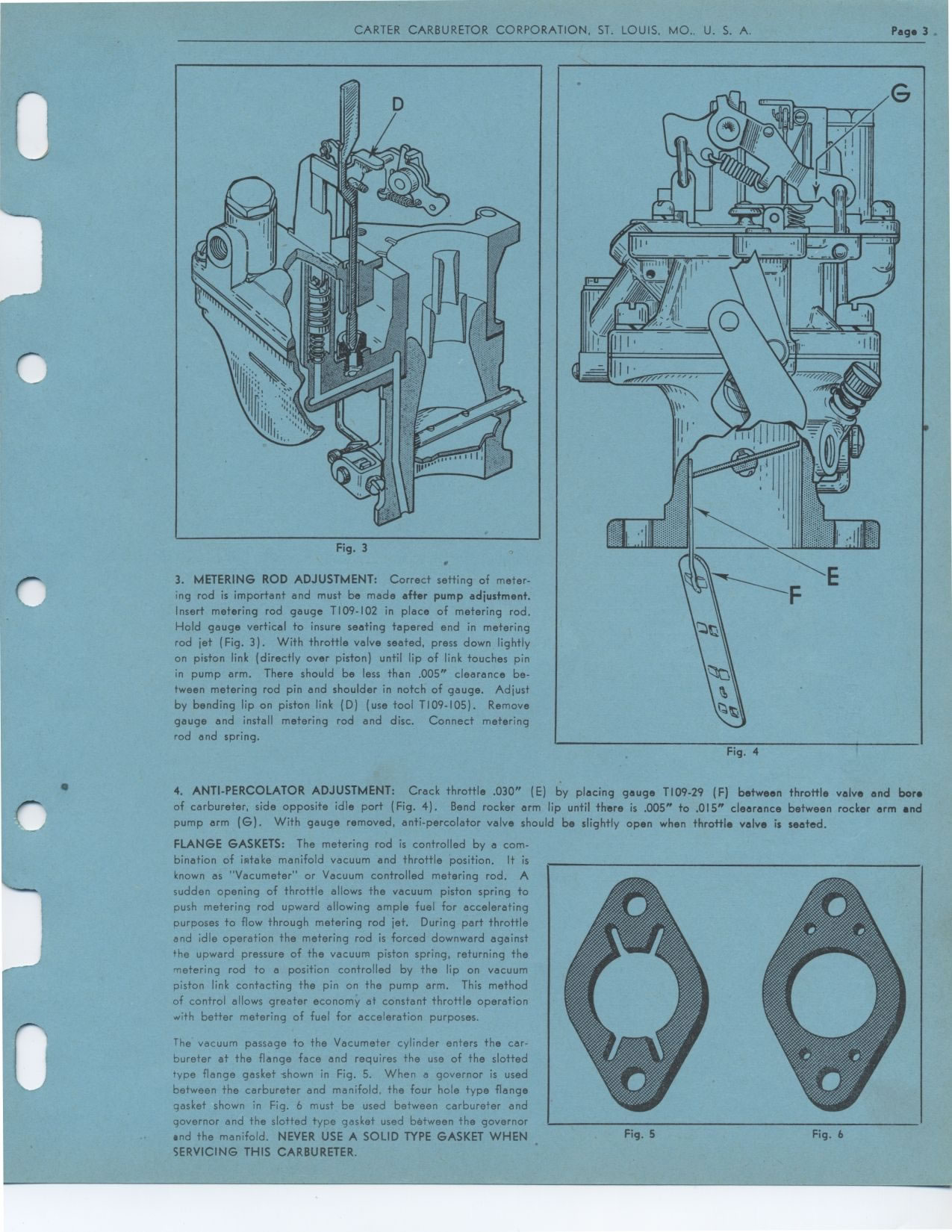
Fig. 3
3. METERING ROD ADJUSTMENT: Correct setting of metering rod is important
and must be made after pump adjustment. Insert metering rod gauge T109-102
in place of metering rod. Hold gauge vertical to insure seating tapered end
in metering rod jet (Fig. 3). With throttle valve seated, press down lightly
on piston link (directly over piston) until lip of link touches pin in pump
arm. There should be less than .005" clearance between metering rod
pin and shoulder in notch of gauge. Adjust by bending lip on piston link
(D) (use tool T109-105). Remove gauge and install metering rod and disc.
Connect metering rod and spring.
Fig. 4
4. ANTI-PERCOLATOR ADJUSTMENT: Crack throttle .030" (E) by placing gauge
T109-29 (F) between throttle valve and bore of carbureter, side opposite
idle port (Fig. 4). Bend rocker arm lip until there is .005" to .015" clearance
between rocker arm and pump arm (G). With gauge removed, anti-percolator
valve should be slightly open when throttle valve is seated.
FLANGE GASKETS: The metering rod is controlled by a combination of intake
manifold vacuum and throttle position. It is known as "Vacumeter" or
Vacuum controlled metering rod. A sudden opening of throttle allows the vacuum
piston spring to push metering rod upward allowing ample fuel for accelerating
purposes to flow through metering rod jet. During part throttle and idle
operation the metering rod is forced downward against the upward pressure
of the vacuum piston spring, returning the metering rod to a position controlled
by the lip on vacuum piston link contacting the pin on the pump arm. This
method of control allows greater economy at constant throttle operation with
better metering of fuel for acceleration purposes.
The vacuum passage to the Vacumeter cylinder enters the carbureter at the
flange face and requires the use of the slotted type flange gasket shown
in Fig. 5. When a governor is used between the carbureter and manifold, the
four hole type flange gasket shown in Fig. 6 must be used between carbureter
and governor and the slotted type gasket used between the governor and the
manifold. NEVER USE A SOLID TYPE GASKET WHEN SERVICING THIS CARBURETER.
Fig. 5 Fig. 6