Skip to: site menu | section menu | main content
1940 Willys Overland Model 440
Page 2 CARTER CARBURETOR CORPORATION, ST. LOUIS. MO.. U.S.A.
SERVICE INSTRUCTIONS
Carbureter No. 450S
TO DISASSEMBLE
Remove carbureter from motor. Use Carter Tool Kit.
1. Remove choker link pin spring, choker connector link and
spring.
2. Remove air horn assembly with all parts attached.
3. Remove idle well plug and gasket assembly.
4. Remove idle well jet.
5. Remove throttle shaft arm and screw assembly and throttle
connector rod.
6. Remove bowl cover with all parts attached.
7. Remove pump spring from pump cylinder in body.
8. Remove low speed jet plug and gasket assembly.
9. Remove low speed jet.
10. Remove idle adjusting screw and spring. I I. Remove metering rod jet
and gasket assembly.
12. Remove nozzle passage plug and gasket assembly.
Fig. I
13. Remove nozzle retainer plug.
14. Remove nozzle and nozzle gasket, using tool T109-55.
15. Remove body flange attaching screws, tube clamp assembly and then remove
flange from body.
16. Remove strainer passage plug and gasket assembly and strainer.
17. Remove intake ball check assembly.
18. Remove discharge disk check assembly.
19. Remove pump jet passage plug and gasket assembly.
20. Remove pump jet.
21. Remove throttle valve screws, throttle valve and throttle shaft and lever
assembly.
22. Remove idle port rivet plug.
23. Remove choke tube bracket assembly.
24. Remove choker valve screws, choker valve and choker shaft and lever assembly.
25. Disassemble all parts from bowl cover.
Clean all castings thoroughly inside and out with a small brush and clean
gasoline. Then blow all passages out with compressed air
'Group all parts as follows:
a. Group all parts controlling the gasoline level. (Fig. 2.)
b. Group all idle system parts. (Fig. I.)Fig. 2
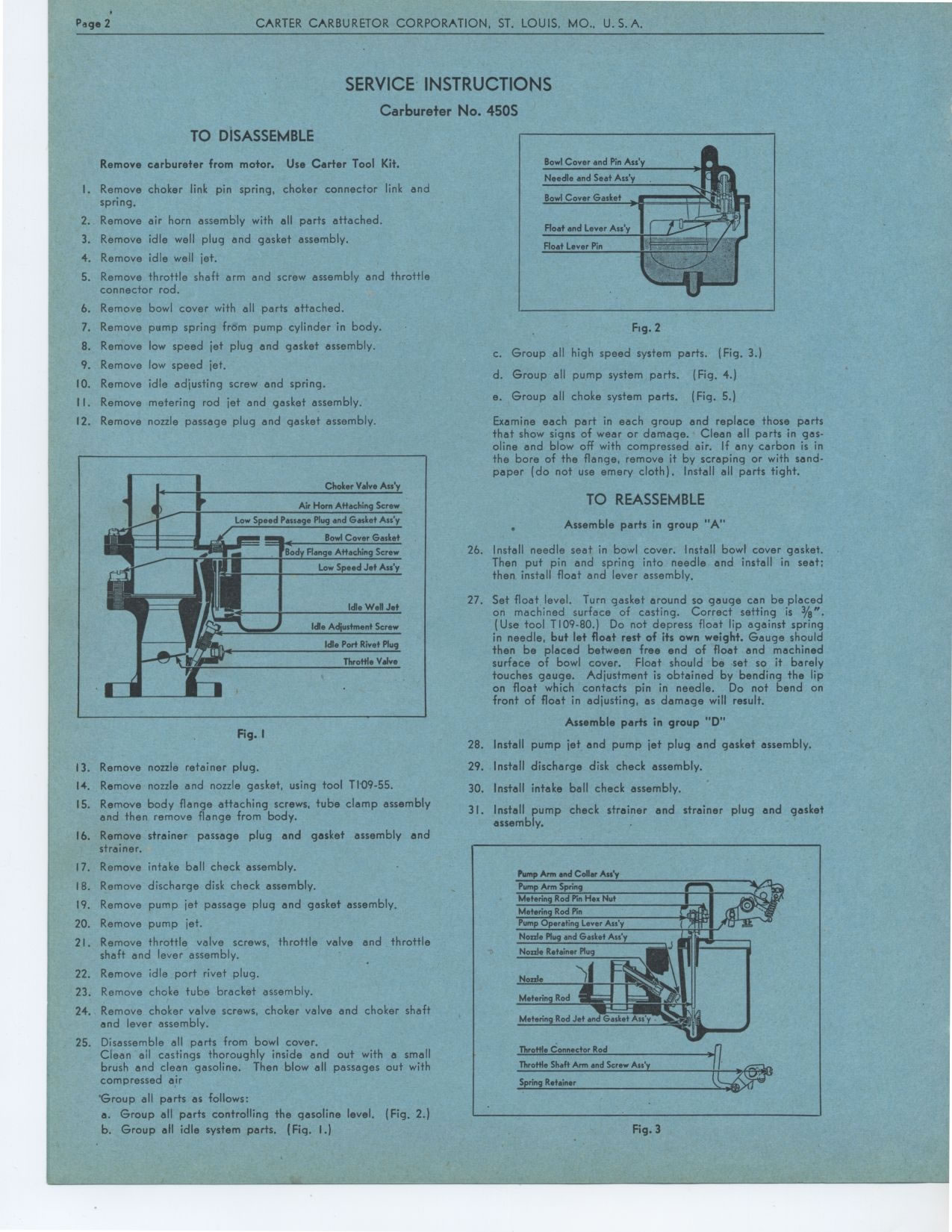
c. Group all high speed system parts. (Fig. 3.)
d. Group all pump system parts. (Fig. 4.)
e. Group all choke system parts. (Fig. 5.)
Examine each part in each group and replace those parts that show signs
of wear or damage. Clean all parts in gasoline and blow off with compressed
air. If any carbon is in the bore of the flange, remove it by scraping or
with sand-paper (do not use emery cloth). Install all parts tight.
TO REASSEMBLE
Assemble parts in group "A"
26. Install needle seat in bowl cover. Install bowl cover gasket. Then put pin and spring into needle and install in seat; then install float and lever assembly.
27. Set float level. Turn gasket around so gauge can be placed on machined
surface of casting. Correct setting is 3/err. (Use tool T109-80.) Do not
depress float lip against spring in needle, but let float rest of its own
weight. Gauge should then be placed between free end of float and machined
surface of bowl cover. Float should be set so it barely touches gauge. Adjustment
is obtained by bending the lip on float which contacts pin in needle. Do
not bend on front of float in adjusting, as damage will result.
Assemble parts in group "D"
28. Install pump jet and pump jet plug and gasket assembly.
29. Install discharge disk check assembly.
30. Install intake ball check assembly.
31. Install pump check strainer and strainer plug and gasket assembly.
Fig. 3
Choker Valve Ass.),
Air Horn Attaching Screw Low Speed Passage Plug and Gasket Ass'y
Bowl Cover Gasket
Body Flange Attaching Screw Low Speed Jet Ass'y
Idle Well Jet
Idle Adjustment Screw
Idle Port Rivet Plug Throttle Valve
Bowl Cover and Pin Ass'y Needle and Seat Asi y
Pump Arm and Collar Ass'y
Pump Arm Spring
Meteri 9 Rod Pin Hex Not
Metering Rod Pin
Pump Operating Lever Ass'y Neale Plug and Gasket Asi y Nossle Retainer Plug
Throttle Connector Rod Throttle Shaft Ann and Screw Ass'y
Spring Retainer