Skip to: site menu | section menu | main content
1935 Chevy TRANSMISSION
Synchro Mesh Transmission (Master Model Passenger Cars and 1/2 Ton Trucks) Construction
The synchro-mesh transmission is designed and
built to meet the needs of present day traffi.; conditions; and
in operation permits even the inexperienced driver to shift gears
smoothly and noiselessly.
The synchro-mesh transmission, used in Chevrolet passenger cars
and % ton trucks, has all the necessary fundamentals for successful
synchromesh operation which have been used by various divisions
of General Motors during the past few years. This transmission
is the finest type built today. Millions of Chevrolet cars driven
for many millions of miles have this same type of transmission
and the owners of these cars and trucks have experienced no mechanical
trouble with them.
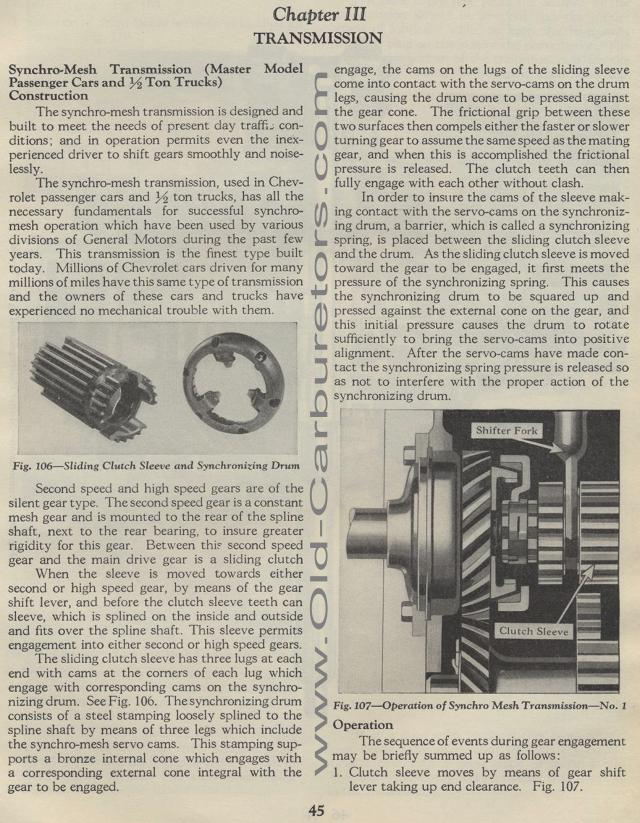
Fig. 106— Sliding Clutch Sleeve and Synchronizing Drum
Second speed and high speed gears are of the silent gear type.
The second speed gear is a constant mesh gear and is mounted to
the rear of the spline shaft, next to the rear bearing, to insure
greater rigidity for this gear. Between this second speed gear
and the main drive gear is a sliding clutch
When the sleeve is moved towards either second or high speed gear,
by means of the gear shift lever, and before the clutch sleeve
teeth can sleeve, which is splined on the inside and outside and
fits over the spline shaft. This sleeve permits engagement into
either second or high speed gears.
The sliding clutch sleeve has three lugs at each end with cams
at the corners of each lug which engage with corresponding cams
on the synchronizing drum. See Fig. 106. The synchronizing drum
consists of a steel stamping loosely splined to the spline shaft
by means of three legs which include the synchro-mesh servo cams.
This stamping sup-ports a bronze internal cone which engages with
a corresponding external cone integral with the gear to be engaged.engage,
the cams on the lugs of the sliding sleeve come into contact with
the servo-cams on the drum legs, causing the drum cone to be pressed
against the gear cone. The frictional grip between these two surfaces
then compels either the faster or slower turning gear to assume
the same speed as the mating gear, and when this is accomplished
the frictional pressure is released. The clutch teeth can then
fully engage with each other without clash.
In order to insure the cams of the sleeve making contact with the
servo-cams on the synchronizing drum, a barrier, which is called
a synchronizing spring, is placed between the sliding clutch sleeve
and the drum. As the sliding clutch sleeve is moved toward the
gear to be engaged, it first meets the pressure of the synchronizing
spring. This causes the synchronizing drum to be squared up and
pressed against the external cone on the gear, and this initial
pressure causes the drum to rotate sufficiently to bring the servo-cams
into positive alignment. After the servo-cams have made con-tact
the synchronizing spring pressure is released so as not to interfere
with the proper action of the synchronizing drum.
Fig. 107— Operation of SynchroMesh Transmission —No.
1
Operation
The sequence of events during gear engagement may be briefly summed
up as follows :
1. Clutch sleeve moves by means of gear shift lever taking up end
clearance. Fig. 107.