Skip to: site menu | section menu | main content
A glance at Fig. 127 shows the sturdy construction and relative position of all of the parts of this transmission.
Operation
Due to the simplicity in construction of the four speed transmission,
there is little that can be said about its operation.
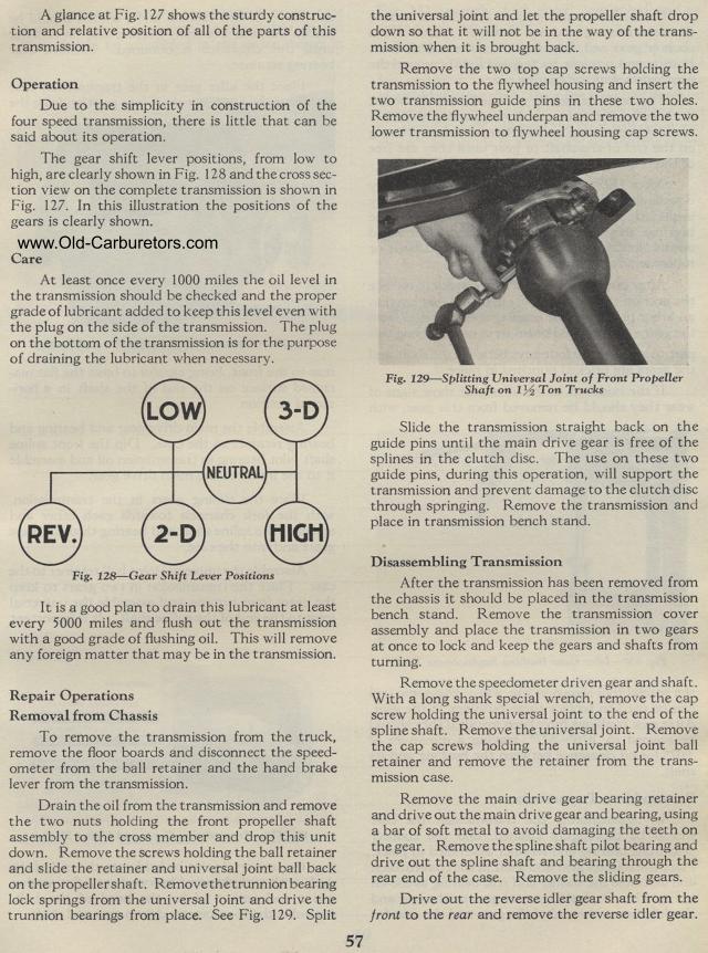
The gear shift lever positions, from low to high, are clearly shown
in Fig. 128 and the cross section view on the complete transmission
is shown in Fig. 127. In this illustration the positions of the
gears is clearly shown.
Care
At least once every 1000 miles the oil level in the transmission
should be checked and the proper grade of lubricant added to keep
this level even with the plug on the side of the transmission.
The plug on the bottom of the transmission is for the purpose of
draining the lubricant when necessary.
It is a good plan to drain this lubricant at least every 5000 miles
and flush out the transmission with a good grade of flushing oil.
This will remove any foreign matter that may be in the transmission.
Repair Operations Removal from Chassis
To remove the transmission from the truck, remove the floor boards
and disconnect the speedometer from the ball retainer and the hand
brake lever from the transmission.
Drain the oil from the transmission and remove the two nuts holding
the front propeller shaft assembly to the cross member and drop
this unit down. Remove the screws holding the ball retainer and
slide the retainer and universal joint ball back on the propeller
shaft. Remove the trunnion bearing lock springs from the universal
joint and drive the trunnion bearings from place. See Fig. 129.
Split
57the universal joint and let the propeller shaft drop down so
that it will not be in the way of the trans-mission when it is
brought back.
Remove the two top cap screws holding the transmission to the flywheel
housing and insert the two transmission guide pins in these two
holes. Remove the flywheel underpan and remove the two lower transmission
to flywheel housing cap screws.
Fig. 129— Splitting Universal Joint of Front Propeller
Shaft on 1 1/2 Ton Trucks
Slide the transmission straight back on the guide pins until the
main drive gear is free of the splines in the clutch disc. The
use on these two guide pins, during this operation, will support
the transmission and prevent damage to the clutch disc through
springing. Remove the transmission and place in transmission bench
stand.
Disassembling Transmission
After the transmission has been removed from the chassis it should
be placed in the transmission bench stand. Remove the transmission
cover assembly and place the transmission in two gears at once
to lock and keep the gears and shafts from turning.
Remove the speedometer driven gear and shaft. With a long shank
special wrench, remove the cap screw holding the universal joint
to the end of the spline shaft. Remove the universal joint. Remove
the cap screws holding the universal joint ball retainer and remove
the retainer from the trans-mission case.
Remove the main drive gear bearing retainer and drive out the main
drive gear and bearing, using a bar of soft metal to avoid damaging
the teeth on the gear. Remove the spline shaft pilot bearing and
drive out the spline shaft and bearing through the rear end of
the case. Remove the sliding gears.
Drive out the reverse idler gear shaft from the front to the rear
and remove the reverse idler gear.
Gear Shift Lever Positions