Skip to: site menu | section menu | main content
Transmission Specifications
Best read by looking at the page image at the bottom.
Gear Ratios: 1931 1932 1933 1934 1935
First Speed: 3.32 3.05 3.02 3.02 3.02
Passenger and 1/2 Ton
Ton 6.165 7.22 7.22 7.23 7.23
Standard 2.802 2.802 2.802
Second Speed: 1.77 1.80 1.70 1.70 1.70
Passenger and % Ton
1% Ton 3.474 3.47 3.47 3.48 3.48
Standard 1.708 1.708 1.708
Third Speed: Direct Direct Direct Direct Direct
Passenger and % Ton
1% Ton 1.746 1.71 1.71 1.71 1.71
Standard Direct Direct Direct
Fourth Speed: Direct Direct Direct Direct Direct
1% Ton
Reverse: 4.2 3.43 3.40 3.40 3.40
Passenger and % Ton
1% Ton 6.297 7.15 7.15 7.15 7.15
Standard 2.802 2.802 2.802
Grease Capacity: 2 pts. 2% pts. 2% pts. 2% pts. 2%z pts.
Passenger and % Ton
1 % Ton 6% pts. 6% pts. 6% pts. 6% pts. 6% pts.
Standad 1% pts. 1 % pts. 1 % pts.
Grease Capacity: 34pt. % pt.
Free-wheeling
NOTE-Use SAE 40 Engine Oil in Fleet Economy .025" to .035" .025" to
.035" .025" to .035" .025" to .035"
Transmissions and Rear Axles. On all other
Models use SAE 90 or SAE 160, depending on cli-
mate conditions.
Rear Synchronizing Spring Clearance
Front Synchronizing Spring Clearance .025" to .035" .025" to
.035" .025" to .035" .025" to .035"
Counter Gear and Thrust Washer Clearance .005" to .025" .005" to
.025" .005" to .025" .005" to .025"
Synchronizing Spring Sizes-Width of Slots: .282" .282" .282" .282"
Rear-White
Rear-Black .292" .292" .292" .292"
Front-Red .173" .173" .173" .173"
Front-Yellow .183" .183" .183" .183"
Front-Green .193" .193" .193" .193"
Front-Blue .203" .203" .203" .203"
Front-Brown .213" .213" .213" .213"
Repair Operations Removal from Chassis
In removing the transmission from the chassis, first remove the
speedometer cable from the torque ball retainer and the hand brake
lever from the frame. Remove the cap screws holding the ball collar
and slip the ball and the collar back on the propeller shaft.
Remove the nuts from the universal joint ring and split the universal
joint. Remove the two top transmission to flywheel housing cap
screws and insert the two transmission guide pins in these holes.
Remove the flywheel underpan and remove the two lower transmission
to flywheel housing cap screws.
Remove the bolts holding the rear of trans-mission to the frame.
Remove the nuts holding the cross member to the universal joint
ball retainer and remove this part.
Slide the transmission straight back on the guide pins until the
main drive gear shaft is free of the splines in the clutch disc.
The use of the two guide pins during this operation will support
the transmission and prevent damage to the clutch disc through
springing. Remove the transmission.
48Disassembly of Transmission
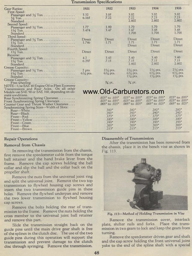
After the transmission has been removed from the chassis, place
it in the bench vise as shown in Fig. 113.
Fig. 113-Method of Holding Transmission in Vise
Remove the transmission cover, interlock plate, shifter rails and
forks. Place the trans-mission in two gears to lock and keep the
gears from turning.
Remove the speedometer driven gear and shaft and the cap screw
holding the front universal joint yoke to the end of the spline
shaft with a special