Skip to: site menu | section menu | main content
Turn the universal joint ball retainer to clear the countershaft and insert one cap screw to hold it in place. Insert counter gear holding tool to bring the counter gear and thrust washers to their correct position. Drive in the countershaft from the FRONT end with the tool acting as a guide, using a lead or soft hammer. The tang on the end of the countershaft should be in a horizontal position.
Remove the one cap screw holding the universal joint ball retainer and move the retainer to its correct position and bolt securely in place, being sure that the gasket between the retainer and the case is in good condition.
Assemble the universal joint front yoke with the trunnion bearings,
which are assembled to the yoke with the chamfered side towards
the yoke, and the front ring to the end of the spline shaft. Bolt
securely in place, using a new flat and lockwasher under the head
of the bolt. This is important as this washer acts as a lock biting
into the ends of the splines on the end of the spline shaft holding
the bolt securely in place.
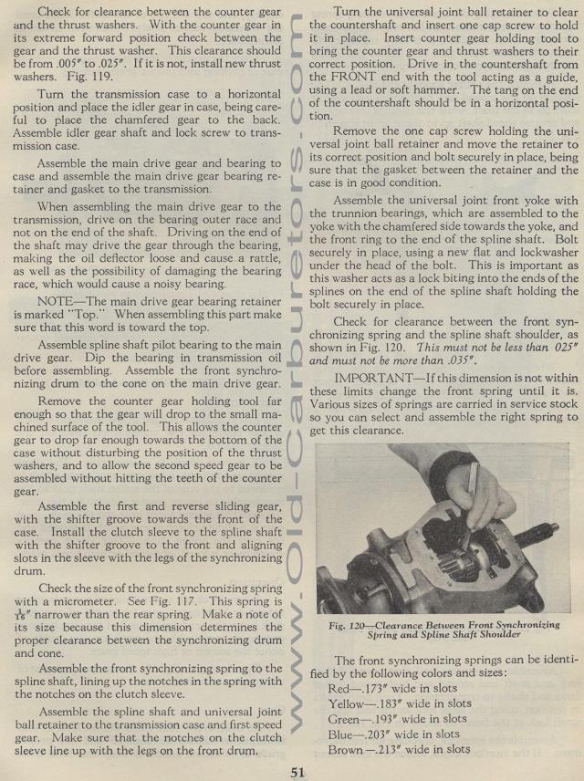
Check for clearance between the front synchronizing spring and
the spline shaft shoulder, as shown in Fig. 120. This must not
be less than 025" and must not be more than .035".
IMPORTANT— If this dimension is not within these limits change
the front spring until it is. Various sizes of springs are carried
in service stock so you can select and assemble the right spring
to get this clearance.
Fig. 120— Clearance Between Front Synchronizing
Spring and Spline Shaft Shoulder
The front synchronizing springs can be identified by the following
colors and sizes:
Red — .173" wide in slots
Yellow — .183" wide in slots
Green-.193" wide in slots
Blue-.203" wide in slots
Brown -.213" wide in slots
Check for clearance between the counter gear and the thrust washers.
With the counter gear in its extreme forward position check between
the gear and the thrust washer. This clearance should be from .005" to
.025". If it is not, install new thrust washers. Fig. 119.
Turn the transmission case to a horizontal position and place the
idler gear in case, being careful to place the chamfered gear to
the back. Assemble idler gear shaft and lock screw to trans-mission
case.
Assemble the main drive gear and bearing to case and assemble the
main drive gear bearing retainer and gasket to the transmission.
When assembling the main drive gear to the transmission, drive
on the bearing outer race and not on the end of the shaft. Driving
on the end of the shaft may drive the gear through the bearing,
making the oil deflector loose and cause a rattle, as well as the
possibility of damaging the bearing race, which would cause a noisy
bearing.
NOTE— The main drive gear bearing retainer is marked "Top." When
assembling this part make sure that this word is toward the top.
Assemble spline shaft pilot bearing to the main drive gear. Dip
the bearing in transmission oil before assembling. Assemble the
front synchronizing drum to the cone on the main drive gear.
Remove the counter gear holding tool far enough so that the gear
will drop to the small machined surface of the tool. This allows
the counter gear to drop far enough towards the bottom of the case
without disturbing the position of the thrust washers, and to allow
the second speed gear to be assembled without hitting the teeth
of the counter gear.
Assemble the first and reverse sliding gear, with the shifter groove
towards the front of the case. Install the clutch sleeve to the
spline shaft with the shifter groove to the front and aligning
slots in the sleeve with the legs of the synchronizing drum.
Check the size of the front synchronizing spring with a micrometer.
See Fig. 117. This spring is is" narrower than the rear spring.
Make a note of its size because this dimension determines the proper
clearance between the synchronizing drum and cone.
Assemble the front synchronizing spring to the spline shaft, lining
up the notches in the spring with the notches on the clutch sleeve.
Assemble the spline shaft and universal joint ball retainer to
the transmission case and first speed gear. Make sure that the
notches on the clutch sleeve line up with the legs on the front
drum,