Skip to: site menu | section menu | main content
Assemble second speed gear thrust washer (bronze) to the spline shaft with the counterbore towards the front and lock in place with the spring retainer which can be assembled to the spline shaft
Thrust Washer Retainer Assembly Tool with the special tool shown in Fig. 116. Assemble the rear synchronizing drum to the spline shaft.
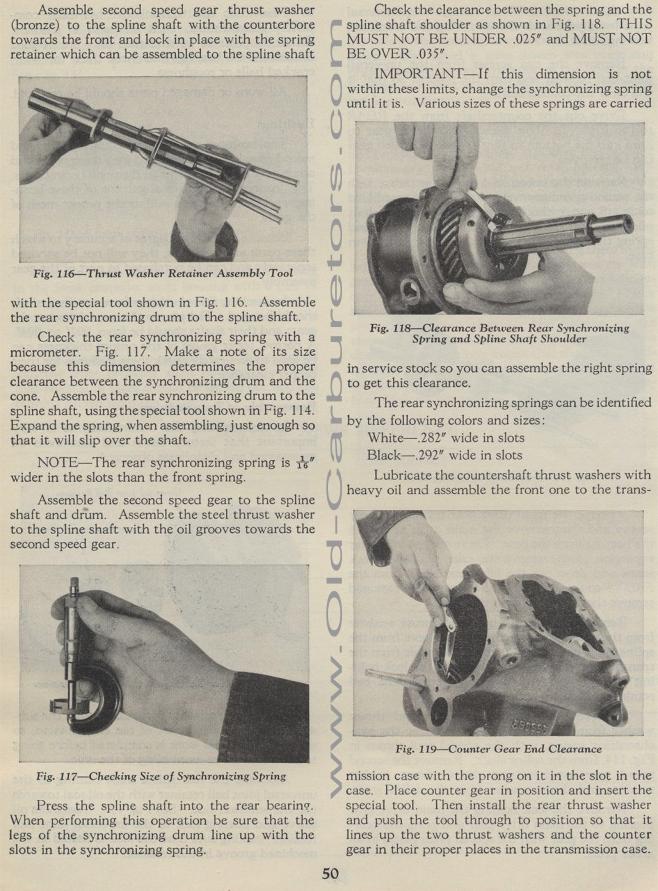
Check the rear synchronizing spring with a micrometer. Fig. 117.
Make a note of its size because this dimension determines the proper
clearance between the synchronizing drum and the cone. Assemble
the rear synchronizing drum to the spline shaft, using the special
tool shown in Fig. 114. Expand the spring, when assembling, just
enough so that it will slip over the shaft.
NOTE— The rear synchronizing spring is is" wider in
the slots than the front spring.
Assemble the second speed gear to the spline shaft and drum. Assemble
the steel thrust washer to the spline shaft with the oil grooves
towards the second speed gear.
Fig. 117— Checking Size of Synchronizing Spring
Press the spline shaft into the rear bearing. When performing
this operation be sure that the legs of the synchronizing drum
line up with the slots in the synchronizing spring.
50
Check the clearance between the spring and the spline shaft shoulder
as shown in Fig. 118. THIS MUST NOT BE UNDER .025" and MUST
NOT BE OVER .03 5".
IMPORTANT— If this dimension is not within these limits,
change the synchronizing spring until it is. Various sizes of these
springs are carried
Fig. 118— Clearance Between Rear Synchronizing
Spring and Spline Shaft Shoulder
in service stock so you can assemble the right spring to get this
clearance.
The rear synchronizing springs can be identified by the following
colors and sizes:
White — .282" wide in slots
Black — .292" wide in slots
Lubricate the countershaft thrust washers with heavy oil and assemble
the front one to the trans-
Fig. 119— Counter Gear End Clearance
mission case with the prong on it in the slot in the case. Place
counter gear in position and insert the special tool. Then install
the rear thrust washer and push the tool through to position so
that it lines up the two thrust washers and the counter gear in
their proper places in the transmission case.