Skip to: site menu | section menu | main content
with the plug on the side of the transmission. The plug on the
bottom of the transmission is for the purpose of draining the lubricant
when necessary.
It is a good plan to drain this lubricant at least every 5000 miles and flush
out the transmission with a good grade of light flushing oil. This will remove
any foreign matter that may be in the transmission.
Transmission Repair Operations
Due to the fact that many of the operations in the repair of this transmission are similar to those of the Master model transmission, we will not attempt to illustrate each one, but will give a list of the operations necessary for a complete overhaul of this transmission in their proper sequence.
Removal from Chassis
Disconnect the brake rods from the rear axle and the "U" bolts
from the axle and springs. Slide the rear axle to the rear until
the propeller shaft is free from the universal joint. Disconnect
the hand brake lever, speedometer cable and the transmission from
the cross member. Remove the two top transmission to flywheel housing
cap screws and insert the guide pins in these holes. Remove the
flywheel underpan and remove the two lower transmission to flywheel
housing cap screws.
Slide the transmission straight back on the guide pins until the
main drive gear shaft is free of the clutch disc hub. These guide
pins protect the clutch disc from damage due to springing during
this operation Remove the transmission from the car and place in
a bench vise for overhauling.
Dissassembly
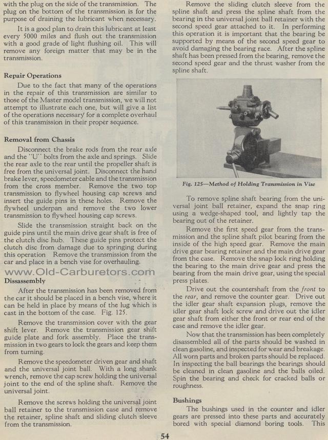
After the transmission has been removed from the car it should
be placed in a bench vise, where it can be held in place by means
of the lug which is cast in the bottom of the case. Fig. 125.
Remove the transmission cover with the gear shift lever. Remove
the transmission gear shift guide plate and fork assembly. Place
the trans-mission in two gears to lock the gears and keep them
from turning.
Remove the speedometer driven gear and shaft and the universal
joint ball. With a long shank wrench, remove the cap screw holding
the universal joint to the end of the spline shaft. Remove the
universal joint.
Remove the screws holding the universal joint ball retainer to
the transmission case and remove the retainer, spline shaft and
sliding clutch sleeve from the transmission.
Remove the sliding clutch sleeve from the spline shaft and press
the spline shaft from the bearing in the universal joint ball retainer
with the second speed gear attached to it. In performing this operation
it is important that the bearing be supported by means of the second
speed gear to avoid damaging the bearing race. After the spline
shaft has been pressed from the bearing, remove the second speed
gear and the thrust washer from the spline shaft.
Fig. 125— Method of Holding Transmission in Vise
To remove spline shaft bearing from the universal joint ball retainer,
expand the snap ring using a wedge-shaped tool, and lightly tap
the bearing out of the retainer.
Remove the first speed gear from the trans-mission and the spline
shaft pilot bearing from the inside of the high speed gear. Remove
the main drive gear bearing retainer and the main drive gear from
the case. Remove the snap lock ring holding the bearing to the
main drive gear and press the bearing from the main drive gear,
using the special press plates.
Drive out the countershaft from the front to the rear, and remove
the counter gear. Drive out the idler gear shaft expansion plugs,
remove the idler gear shaft lock screw and drive out the idler
gear shaft from either the front or rear end of the case and remove
the idler gear.
Now that the transmission has been completely disassembled all
of the parts should be washed in clean gasoline, and inspected
for wear and breakage. All worn parts and broken parts should be
replaced. In inspecting the ball bearings the bearings should be
cleaned in clean gasoline and the balls oiled. Spin the bearing
and check for cracked balls or roughness.
Bushings
The bushings used in the counter and idler gears are pressed into
these parts and accurately bored with special diamond boring
tools. This