Skip to: site menu | section menu | main content
REAR AXLE ASSEMBLY AND REAR WHEELS
Passenger Cars and 1/2 Ton Trucks
Construction
The rugged semi-floating rear axle is mounted in a sturdy one-piece
banjo-type housing. This type of housing forms an extremely rigid
support for the rear springs and rear wheel bearings. It permits
easy inspection or adjustment of the ring gear and pinion gears.
The differential ring gear is mounted to a strong one-piece malleable
iron differential case by means of twelve special rivets.
The differential
case is supported in the differential carrier by two heavy ball
bearings, which in turn are held in position by the differential
carrier yokes. The adjusting nuts are threaded into these yokes
and permit a very close adjustment of these gears, assuring perfect
alignment and positive tooth contact between the ring gear and
pinion.
The chromium nickel steel rear axle drive gears are spiral bevel
cut, giving them unusual strength, permitting the engagement of
more than one tooth at a time. This feature assures extremely quiet
operation.
The rear axle drive pinion is forged integral with the splined
stub shaft. The splines of this stub shaft mate with a female splined
sleeve which is welded to the propeller shaft.
The propeller shaft is a rigid large diameter tubular shaft supported
on its forward end by a plain bearing mounted in the housing. The
tubular type of construction, of the propeller shaft, gives it
more strength and less weight and lessens its tendency to "whip" at
high speeds.
Operation
The power is transmitted from the propeller shaft through the pinion
and ring gear to the differential and axle shafts to the rear wheels.
The differential gears permit one wheel to turn faster than the
other, which condition exists when the car is turning a corner.
When the car is traveling in a straight line and the rear wheel
traction is equal on both wheels, the differential gears do not
turn. The differential gears compensate for the twisting motion
which would take place if the axle were one piece shaft from wheel
to wheel and one wheel was forced to travel faster than the other
Care
There is little to be said about the care of the rear axle, as
all that is required is proper lubrication. The oil level should
be checked at intervals of 1000 miles by removing the plug in the
axle housing cover and seeing that the oil level is even with it.
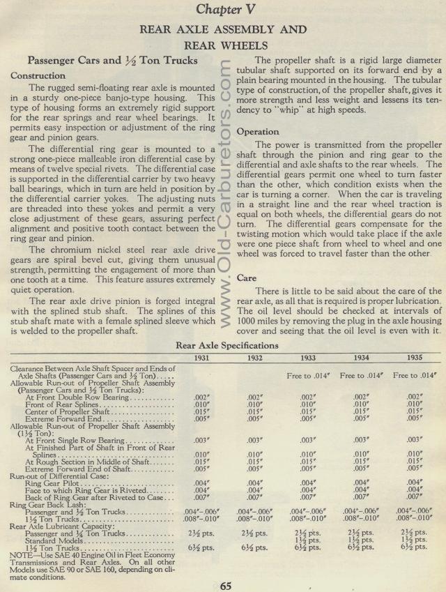
Rear Axle Specifications Look at the
page image below to read this table.
1931 1932 1933 1934 1935
Clearance Between Axle Shaft Spacer and Ends of Free to .014" Free to .014" Free
to .014"
Axle Shafts (Passenger Cars and A Ton)
Allowable Run-out of Propeller Shaft Assembly .002" .002" .002" .002" .002"
(Passenger Cars and A Ton Trucks):
At Front Double Row Bearing
Front of Rear Splines .010" .010" .010" .010" .010"
Center of Propeller Shaft .015" .015" .015" .015" .015"
Extreme Forward End .005" .005" .005" .005" .005"
Allowable Run-out of Propeller Shaft Assembly .003" .003" .003" .003" .003"
(1 % Ton):
At Front Single Row Bearing
At Finished Part of Shaft in Front of Rear .010" .010" .010" .010" .010"
Splines
At Rough Section in Middle of Shaft .015" .015' .015" .015" .015'
Extreme Forward End of Shaft .005" .005" .005" .005" .005"
Run-out of Differential Case: .004" .004" .004" .004" .004"
Ring Gear Pilot
Face to which Ring Gear is Riveted .004" .004" .004" .004" .004"
Back of Ring Gear after Riveted to Case .007" .007" .007" .007" .007"
Ring Gear Back Lash: .004"-.006" .004"-.006" .004"-.006" .004"-.006" .004"-.006"
Passenger and A Ton Trucks
1A Ton Trucks .008"-.010" .008"-.010" .008"-.010" .008"-.010" .008"-.010"
Rear Axle Lubricant Capacity: 2A pts. 2A pts. 2% pts. 2% pts. 2% pts.
Passenger and % Ton Trucks
Standard Models 1 A pts. 1 A pts. 1% pts.
1A Ton Trucks 6A pts. 6A pts. 6A pts. 6% pts. 6A pts.
NOTE-Use SAE 40 Engine Oil in Fleet Economy
Transmissions and Rear Axles. On all other
Models use SAE 90 or SAE 160, depending on cli-
mate conditions.
