Skip to: site menu | section menu | main content
preventing any chance of misalignment or slip-ping. It is good
practice to insert and head one rivet at a time, then turn the
case half-way around and insert and head a rivet at this point.
Turn the case and head the rivet in between the two rivets already
headed. Insert and head rivet opposite this one. Remove bolts and
insert and head rivets in all other open holes.
The differential side bearings should be assembled to the case with the thick
side or side marked "thrust here" towards the case with the special
driver shown in Fig. 155.
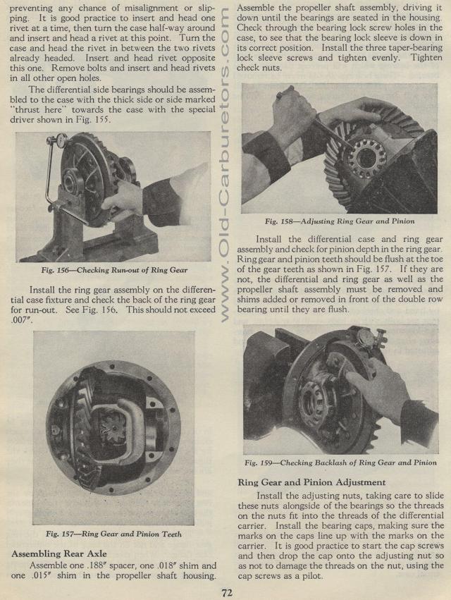
Checking Run-out of Ring Gear
Install the ring gear assembly on the differential case fixture and check the back of the ring gear for run-out. See Fig. 156. This should not exceed .007".
Fig. 157— Ring Gear and Pinion Teeth
Assembling Rear Axle
Assemble one .188" spacer, one .018" shim and one .015" shim
in the propeller shaft housing.
72Assemble the propeller shaft assembly, driving it down until
the bearings are seated in the housing. Check through the bearing
lock screw holes in the case, to see that the bearing lock sleeve
is down in its correct position. Install the three taper-bearing
lock sleeve screws and tighten evenly. Tighten check nuts.
Fig. 158— Adjusting Ring Gear and Pinion
Install the differential case and ring gear assembly and check
for pinion depth in the ring gear. Ring gear and pinion teeth should
be flush at the toe of the gear teeth as shown in Fig. 157. If
they are not, the differential and ring gear as well as the propeller
shaft assembly must be removed and shims added or removed in front
of the double row bearing until they are flush.
Fig. 159— Checking Backlash of Ring Gear and Pinion
Ring Gear and Pinion Adjustment
Install the adjusting nuts, taking care to slide these nuts alongside
of the bearings so the threads on the nuts fit into the threads
of the differential carrier. Install the bearing caps, making sure
the marks on the caps line up with the marks on the carrier. It
is good practice to start the cap screws and then drop the cap
onto the adjusting nut so as not to damage the threads on the nut,
using the cap screws as a pilot.
