Skip to: site menu | section menu | main content
Differential Side Bearing Puller
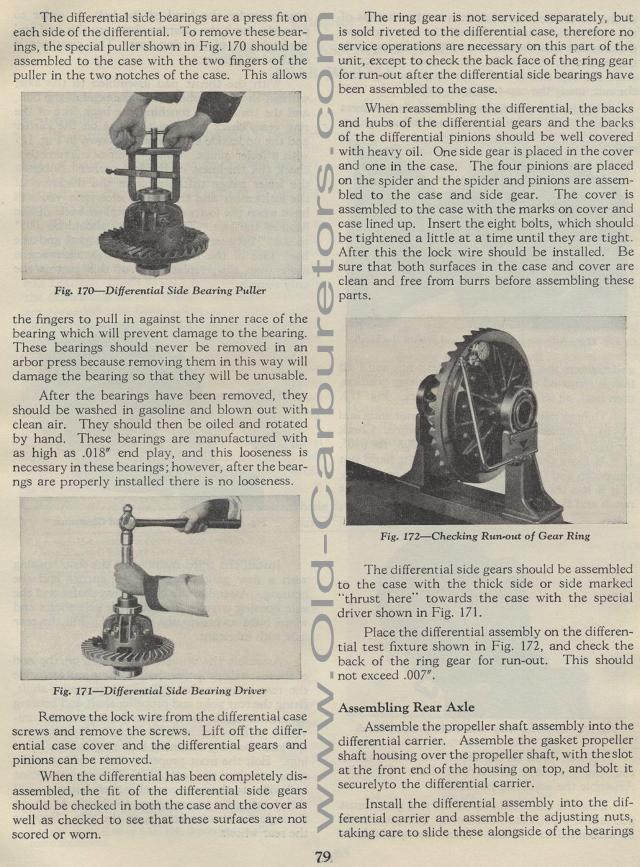
The differential side bearings are a press fit on each side of the differential. To remove these bearings, the special puller shown in Fig. 170 should be assembled to the case with the two fingers of the puller in the two notches of the case. This allows the fingers to pull in against the inner race of the bearing which will prevent damage to the bearing. These bearings should never be removed in an arbor press because removing them in this way will damage the bearing so that they will be unusable.
After the bearings have been removed, they should be washed in
gasoline and blown out with clean air. They should then be oiled
and rotated by hand. These bearings are manufactured with as high
as .018" end play, and this looseness is necessary in these
bearings; however, after the bearngs are properly installed there
is no looseness.
Fig. 171— Differential Side Bearing Driver
Remove the lock wire from the differential case screws and remove
the screws. Lift off the differential case cover and the differential
gears and pinions can be removed.
When the differential has been completely disassembled, the fit
of the differential side gears should be checked in both the case
and the cover as well as checked to see that these surfaces are
not scored or worn.
The ring gear is not serviced separately, but is sold riveted to
the differential case, therefore no service operations are necessary
on this part of the unit, except to check the back face of the
ring gear for run-out after the differential side bearings have
been assembled to the case.
When reassembling the differential, the backs and hubs of the differential
gears and the backs of the differential pinions should be well
covered with heavy oil. One side gear is placed in the cover and
one in the case. The four pinions are placed on the spider and
the spider and pinions are assembled to the case and side gear.
The cover is assembled to the case with the marks on cover and
case lined up. Insert the eight bolts, which should be tightened
a little at a time until they are tight. After this the lock wire
should be installed. Be sure that both surfaces in the case and
cover are clean and free from burrs before assembling these parts.
Fig. 172— Checking Run-out of Gear Ring
The differential side gears should be assembled to the case with
the thick side or side marked "thrust here" towards the
case with the special driver shown in Fig. 171.
Place the differential assembly on the differential test fixture
shown in Fig. 172, and check the back of the ring gear for run-out.
This should not exceed .007".
Assembling Rear Axle
Assemble the propeller shaft assembly into the differential carrier.
Assemble the gasket propeller shaft housing over the propeller
shaft, with the slot at the front end of the housing on top, and
bolt it securely to the differential carrier.
Install the differential assembly into the differential carrier
and assemble the adjusting nuts, taking care to slide these alongside
of the bearings
